H4 head and side light wiring W114

Page may contain affiliate links. Please see terms for details.

Charles Morgan

MB Enthusiast
Joined
Feb 2, 2010
Messages
8,206
Car
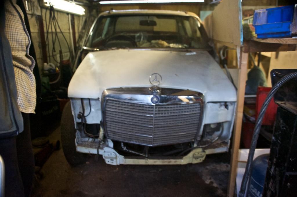
Mercedes 250CE W114, Alfa Romeo GT Coupe 3.2 V6
Right, some help needed, as to paraphrase Winnie the Pooh, I am a bear of very little brain and electrical circuits bother me.

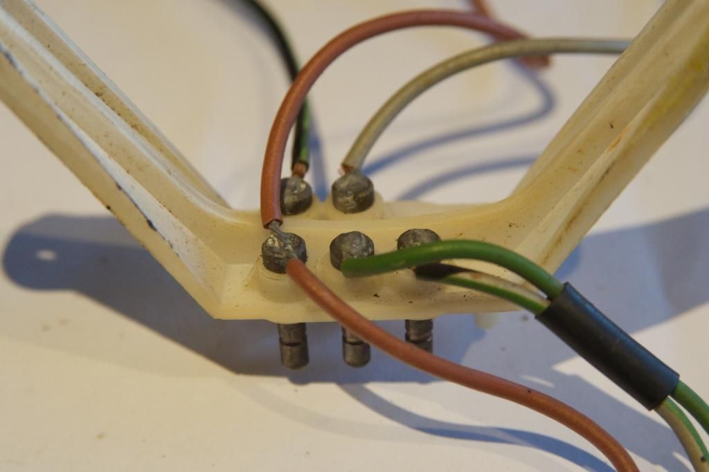
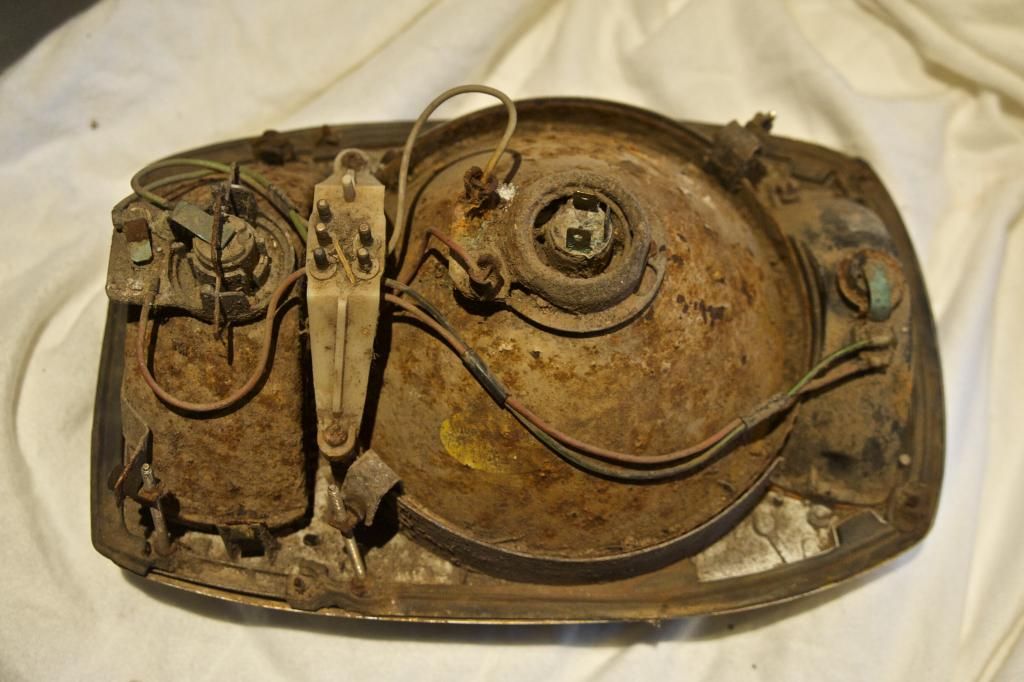
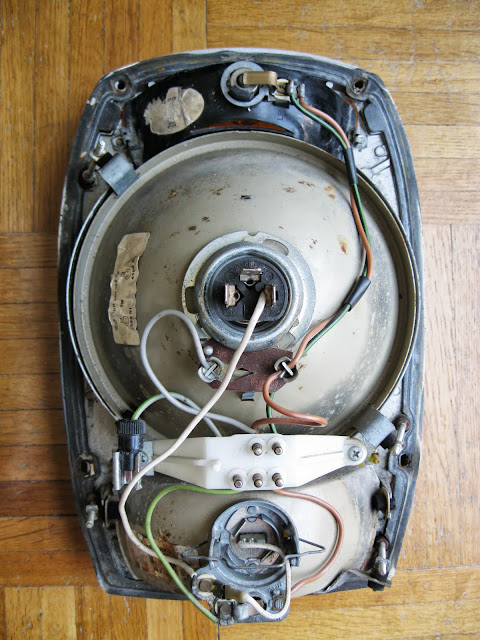
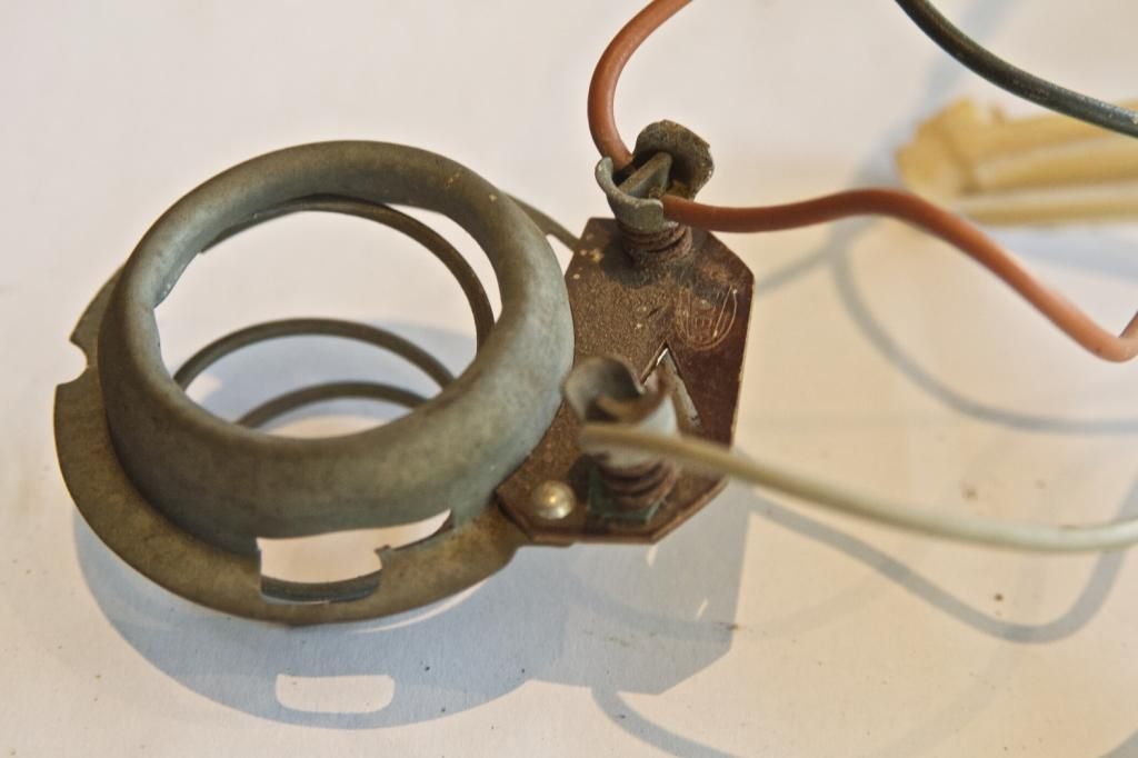
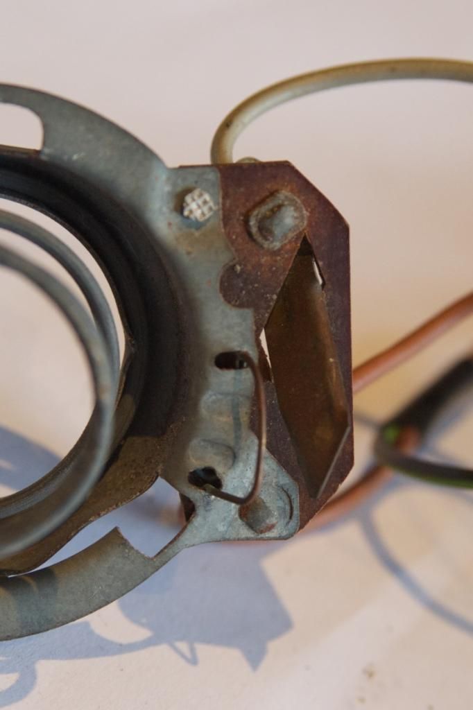
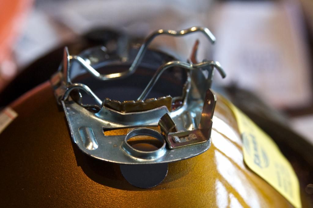
My old headlight reflectors for my W114 house side and headlights. Despite not being for H4 bulbs there were H4 bulbs in each. There are two connections on the fixing. One for sidelights connected by a single grey wire and one for the headlights connected by brown wire to a socket that is also attached to the sidelight bulb. The brown wire goes on to the indicator lights and comes from the same connection that sends a like brown wire to the fog lights. Picture A & B shows the main beam terminal on both sides - it is difficult to make out but the grey connector for the sidelight is mounted into material that is not conductive.

w114lightold2_zps994cfc42.jpg


w114lightold_zps50d88e2f.jpg


I am confused as to how with only two connectors a separate headlight and sidelight circuit could be maintained but let that pass pro tem.

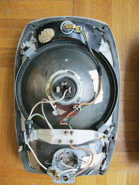
I bought two unused reflectors made in Turkey under license. This is clearly designed for H4 bulbs. As can be seen from Picture C there is only one terminal on the central mount. I assume therefore the bulb connectors that fit the new mount are set up differently to the old ones.

w114lightnew_zpsbb6e418b.jpg


I have new H4 connectors with three leads (I am assuming Positive, Negative and Earth) one black, one white and one blue. Could someone kind give me a means of pulling together with the existing wires and or the new H4 connector (and indeed any other bit of wire I may be missing) so that I can connect up the headlights and the sidelights and they will all work when connected to the loom of the car (assuming that works). I have been puzzling over this for hours.

If for MOT reasons I don't need sidelights I can happily live without as dipped beam is far more sensible.
 
Last edited:
2 wires could be the feeds, relying on a separate connection somewhere to the frame body as the earth?
 
H4 bulbs have three connections one low/dipped beam, one high beam and a common earth. there should be a three pronged connector as part of the loom that plugs onto the back of the bulb.
shopping


socket_wiring_diagram.jpg
the single connector on your new plate is an earth connector and I cant see how you will get a positive feed to the centre contact of the sidelight bulb
 
Last edited:
Hi Charles, not sure if this exactly answers your questions, but it is a start.
In pic 'C' (the new reflector) the sidelight should be in a bulb with its own (metal) holder. This will have a single spade terminal to accept the sidelight feed. This is the grey wire. (could be grey/black for left, grey/red for right.
The spring clip on the side makes contact with the body of the bulb holder and should have a n earth. This will be the brown wire which will need a spade connector.

That is the sidelight sorted.

For the H4 headlight bulb you need the three wires. Main, Dip and Earth. You need a seperate earth to this as the bulb holder is only crimped into the reflector and over time will not give a good earth.

SO
Main should be a white wire, dip should be a yellow wire and earth brown. - you may find that the earth for the sidelight and headlight bulbs are spliced together in the housing.

On the old setup I think that the bulb would have pushed into an interference fit grommet in the reflector, and the large round holder would turn about 30 degrees to both hold in the headlamp bulb, and make contact with the sidelight bulb.

Does that answer the question(s)?
 
That is very helpful Ted.

The one thing missing is an obvious connector for dipped / main (whichever it is) on the connections. What is interesting is the fog lamp has space and connections for two bulbs - I'm beginning to wonder if the fog lamp is actually dipped- it has an adjuster too, which would be odd for a fog lamp Otherwise there is no possible way short of mechanical dipping (which is not in evidence) that a single feed could power both high and low.

w114lightloom_zpsace88fe6.jpg
 
Ah! I think that is it.
The connector you have just posted shows two earths (brown), indicator (black green) - the other side indicator will be black/white, sidelight (grey) and what definitely looks like main/dip -green, green&white - the fact they are also taped together adds weight to this.
Forget my earlier comment about white and yellow - this must be for later models.

Strange though - from memory the bottom lens is fog, and the one above is the main/dip unit.
 
Last edited:
Indeed - the bottom one is fog (which is where the green/white and green leads go), and the main dip is the centre unit with no obvious wiring for anything other than sidelights.
 
As a rule of thumb MERCEDES always use brown insulation rather than black on their earth wires whatever the other supply wire colours are. Please excuse me if I'm stating the obvious.:eek:
 
Charles - I've looked more closely at your headlight pics on the other thread.
My first thought was that the wiring has been messed around with, but it looks original in thos photos.

If it were me, I would put a testlight on those green/green/white wires and look at what lights up when switched to main, dip, and fog.

Certainly a strange one as that bottom lens is definitely fog, and the upper one is definitely 'headlight'
 
For completeness the old lamp set up - I had the blinding idea that I'd screwed up (normally the safest assumption) but clearly something not right.

Of course at present testing not possible but should become possible later on. I just wanted to finish this job so something at least was sorted!

Headlightrear_zpsdf6531ea.jpg
 
According to all diagrams except the oldest (which has an extra light called the clearance light that I can't see) there are 5 lights (each with their own connection) and an earth lead. Now my loom has five connectors.

(wire colours are not all the same as the diagram but that is by the by).

The possibility I need to check is that there is an additional connector at the car end that connects to the main reflector connectors which currently only have one wire in rather than the two the wiring diagrams suggest. Possibly the main beam?

What I do know is the main bulbs are H4 designs which I don't think are contemporary.

What fun this all is. I really must get the car over here.
 
Last edited:
Clearance lights are designed for certain markets which are supposed to indicate the vehicle's width and height- you see them often on pickups and trucks. I imagine Mercedes included these in anticipation for the American market and then found they weren't required?
1.jpg
 
That makes sense, my indicator reflector has room for one but no wiring for one.
 
Each has a different set up. :doh:

My head hurts. Unless I'm mistake the extra wiring to the right hand H4 type connector would be common (earth or negative).
 
Looks like it's the parking light missing on one side. I assume it must be a French thing!
 
Right. I think I have it.
First of all, those French ones either aren't a pair or maybe have a single 'parking light' designed to be on the offside - note also that one has an extra pin on the connector plug for this.
Both of them have sidelights - the same as yours, Charles - run from the large connector on the main reflector. These are the grey and brown (earth wire)
Now the interesting bit. I think there is an additional three pin socket in the headlamp bowl (in the wing) that you have missed. This plugs directly onto the back of the bulb in the main reflector to give main and dip beam.
The wire that goes from that bulb to the one in the 'foglight' is simply a tap. This will then illuminate the 'foglight' whenever the dip beam is on.
Last of all there is a black fly plug clamped in the headlamp unit on both of them.
My theory on this is that it is possible to use this along with a fly lead to change the function of the lamp assembly lighting depending on the territory the car is in. This would obviously need an additional switch or a change in the way the headlamp works.
Now the last paragraph may seem a little far fetched but the rest of it certainly makes some sense to me.
More than happy to read any other theories!
 
All makes sense Ted, I'd come to a similar conclusion. As the car is over the road in the neighbour's garage I can't check it but a photo in really bad light from a few weeks ago does hint at two connectors. (there are currently no wings!)

114front_zps3f054d74.jpg
 
Last edited:
Update - numerous extra wiring floating around in the headlamp area, so I think that would solve it all.

Unless it doesn't!
 

Users who are viewing this thread

Back
Top Bottom