grober
MB Master
ECU ignition output transistors
Came across some useful discussions on the replacement of ignition output transistors for engine ECU's which might be of help to some folks on here.
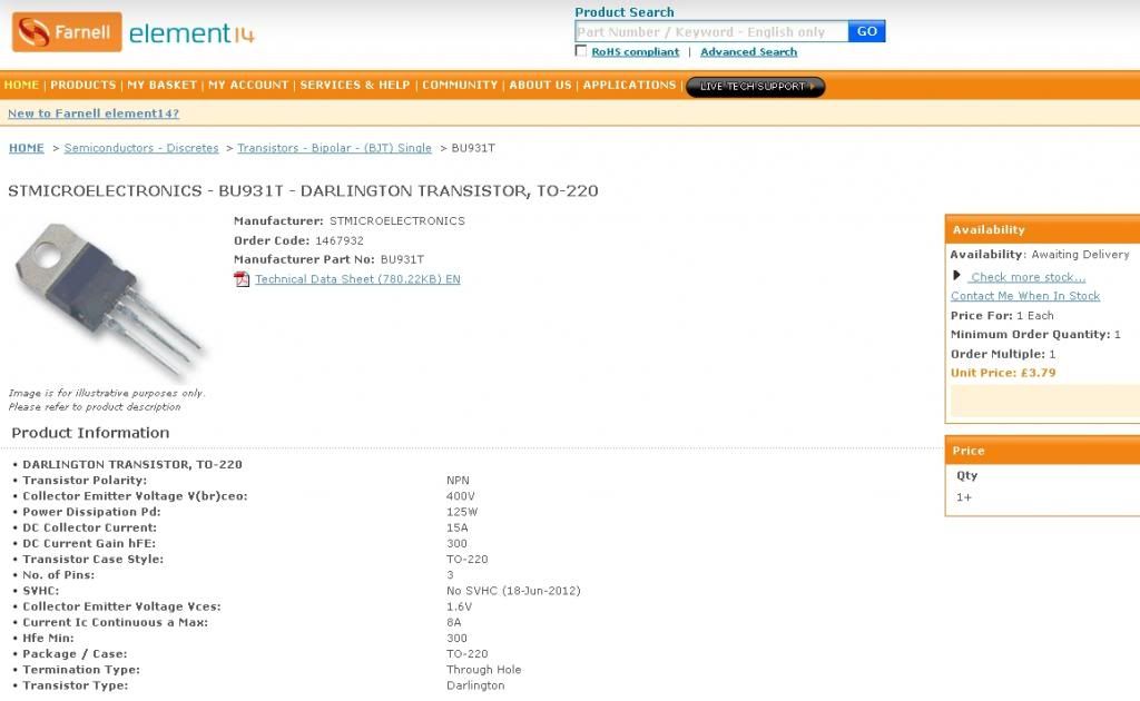
The transistor you're looking for is an NPN Darlington with (IIRC) 20A Icmax, and something like 100-200V Vcemax
Pay attention to the characteristic "diode forward voltage" - this is the voltage that has to be overcome in order to turn transistor on. The value of 2.5V listed for these transistors is around the point at which logical "0" turns into "1" for integrated circuits. This is what we have here - a chip controls these transistors sending out logical "1" in sequential manner. Values below this voltage - say common .7 for ordinary transistors is no good, since it can be overcome by logical "0" which is not desirable.
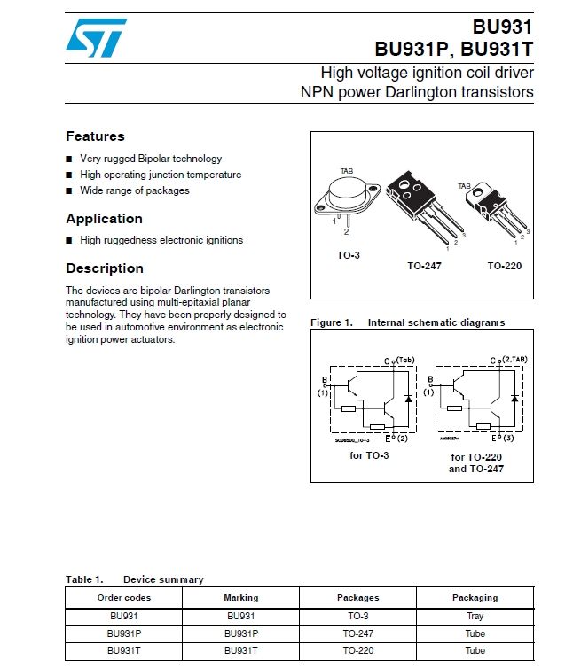
The transistor suggested by Dieselman the BU931 would appear to fit the bill. Available here. STMICROELECTRONICS|BU931-T|DARLINGTON TRANSISTOR, TO-220 | Farnell United Kingdom
If I remember correctly the transistors are glued to their heat sink and that page also lists a suitable adhesive the transistor spec sheet is here
http://www.st.com/stonline/products/...re/ds/1004.pdf
note the transistor is available in alternative packages but you need the TO-247 one.
p.s. Don't know if this "technology" would apply to 90's cars rather than the most up to date models or not but given they are often just switching to ground.
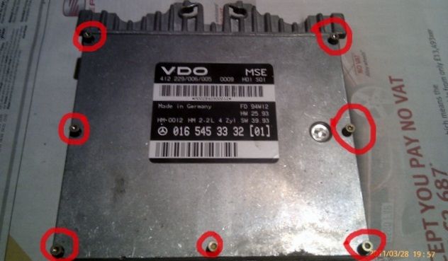
The following courtesy of forum member Algorithmus who performed a successful repair. You will need a male TX10torx bit /screwdriver to open the unit. 7screws on the front. 9screws on the back.
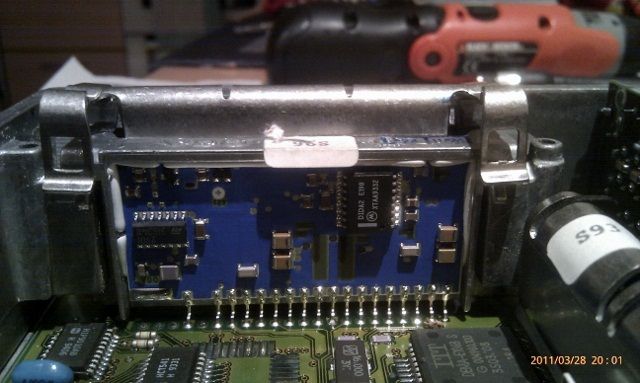
Remove the front cover of ECU,
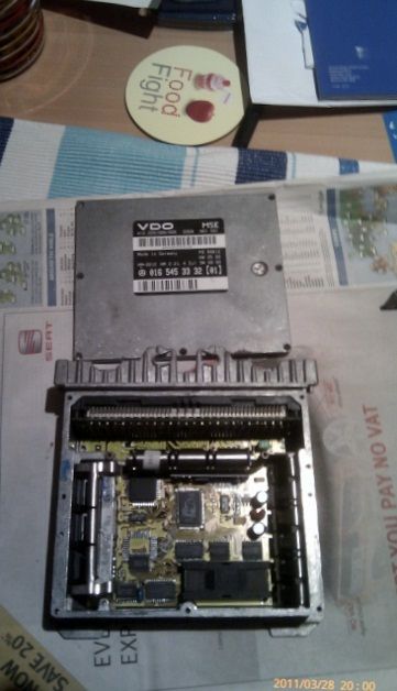
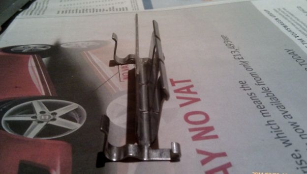
Remove transistor securing metal spring clip assembly. Locates the transistors but also functions as a heat transfer unit to the outer case.The transistors are behind the blue panel
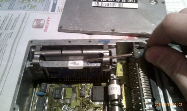
Lift up the 2 clips on the side using a flat screwdriver on both sides of the clip
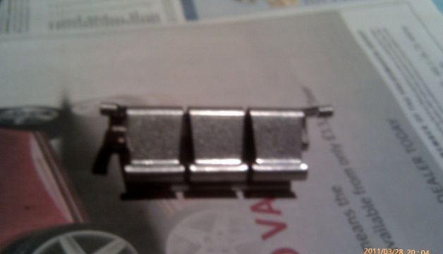
It can hold down 2 or 3 transistors depending on whether the car is 4 or 6 cylinder= 2 or 3 ignition coils
Only then remove the bottom cover [ avoids damage to the PRINTED CIRCUIT BOARD] to expose where the transistors are soldered into the circuit. Following successful renewal Reassemble making sure the transistors make good thermal contact with their metal heatsink assembly/clip - some heatsink paste might be useful here. Precise detail on how to reassemble the unit is best gained from careful observation of how it came apart-- some digital photos may help remind you.
Some pics courtesy of Algorithmus.
Came across some useful discussions on the replacement of ignition output transistors for engine ECU's which might be of help to some folks on here.
The transistor you're looking for is an NPN Darlington with (IIRC) 20A Icmax, and something like 100-200V Vcemax
Pay attention to the characteristic "diode forward voltage" - this is the voltage that has to be overcome in order to turn transistor on. The value of 2.5V listed for these transistors is around the point at which logical "0" turns into "1" for integrated circuits. This is what we have here - a chip controls these transistors sending out logical "1" in sequential manner. Values below this voltage - say common .7 for ordinary transistors is no good, since it can be overcome by logical "0" which is not desirable.
The transistor suggested by Dieselman the BU931 would appear to fit the bill. Available here. STMICROELECTRONICS|BU931-T|DARLINGTON TRANSISTOR, TO-220 | Farnell United Kingdom
If I remember correctly the transistors are glued to their heat sink and that page also lists a suitable adhesive the transistor spec sheet is here
http://www.st.com/stonline/products/...re/ds/1004.pdf
note the transistor is available in alternative packages but you need the TO-247 one.
p.s. Don't know if this "technology" would apply to 90's cars rather than the most up to date models or not but given they are often just switching to ground.
The following courtesy of forum member Algorithmus who performed a successful repair.
You will need a male TX10torx bit /screwdriver to open the unit. 7screws on the front. 9screws on the back.Remove the front cover of ECU,
Remove transistor securing metal spring clip assembly. Locates the transistors but also functions as a heat transfer unit to the outer case.The transistors are behind the blue panel
Lift up the 2 clips on the side using a flat screwdriver on both sides of the clip
It can hold down 2 or 3 transistors depending on whether the car is 4 or 6 cylinder= 2 or 3 ignition coils
Only then remove the bottom cover [ avoids damage to the PRINTED CIRCUIT BOARD] to expose where the transistors are soldered into the circuit. Following successful renewal Reassemble making sure the transistors make good thermal contact with their metal heatsink assembly/clip - some heatsink paste might be useful here. Precise detail on how to reassemble the unit is best gained from careful observation of how it came apart-- some digital photos may help remind you.
Some pics courtesy of Algorithmus.