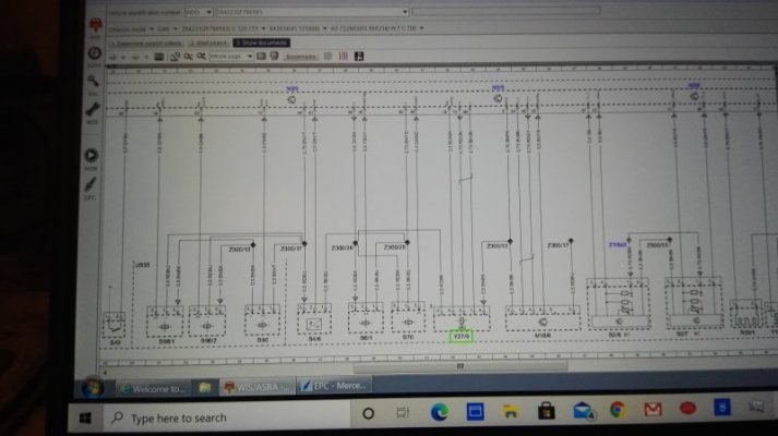
Hi all, well have I got a problem! Get your head around this if you can. My 2011, C350 CDI (204223)OM642 recently went into limp mode with a max rev of 2800rpm. Mileage is 68000 miles
It gave a code P0402 (14A700) excess flow...
I checked
EGR, found signal problem and replaced EGR. (MB)
Pressure sensor EGR gas A0071534328 replaced (MB)
Pressure sensor charge air A0061539928 replaced
Air intake temp sensor replaced - see comment below #
DPF pressure sensor A0061539528 replaced (MB)
DPF pressure pipes removed and checked - all clean and clear.
Manifolds and associated pipework recently removed (5000miles back) and cleaned of all carbon deposits
Swirl flap motor bypassed with 4.7kohm resistor.
Intercooler pipework checked
PCV rear seal changed
MAF sensors input/output checked
No signs of any air leaks (although could do with a proper smoke test) - testes with smoke on outside looking for air suction.
Turbo vanes free to move and actuator functioning correctly and receiving correct voltage.
Voltages checked on above sensors
Scan shows pressures flow etc all correct
DPF has ash content of 0.01g and soot content 4.51g, so ok
Have discondected battery and allow ecu capacitors to drain to reset ecu
Supply from ecu to above electrical components all correct at either 12v or 5 volt where required.
All this and I have the same problem still!
#Odd thing though, the first air temp sensor I fitted was a generic one which was meant to be suitable for this car but it gave a code for it. After fitting it the P0402 went (well briefly at least). I put the old original temp sensor back in and the temp sensor code went but the P0402 returned. I am currently waiting for a MB Temp A6511530028 sensor.
If there are any geniuses out there I would appreciate any help.
Cheers


