RoundOzBenz
New Member
- Joined
- Mar 31, 2014
- Messages
- 20
- Car
- W124 E220
Hi,
I have been an avid reader of posts on this forum for a year or so now and have been able to resolve various minor issues with my beloved W124 E220 (M111.960) - thanks to all the members out there. Time for my first post to the board...
The car has been immensely reliable over the years, save for a voltage regulator fault which cost me a new battery, alternator, comfort module and an obscenely botched repair job (which I resorted to rectifying myself). Anyway, that is another story.
The problem here, and I have read nearly all the related posts is the old issue of stalling/idling issues for the M111. I built a fault-code reader as described here, and received two pulses from the HFM system indicating one or more of the following:
- Engine Coolant Temperature Sensor - Short Circuit
- Engine Coolant Temperature Sensor - Open Circuit
- Engine Coolant Temperature Sensor - Signal Incorrect
- Engine Coolant Temperature Sensor - Intermittent Contact
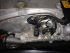
That led me to the three sensors mounted under the plastic shield at the front of the engine (see photo).
All three are negative temperature coefficient sensors, based (partly) on a workshop manual I have, as well as looking up the equivalent replacement parts in a decent automotive sensor supplier's catalogue.
My problem is, other than this I have no further reliable information regarding resistance values over the temperature range. Unfortunately the manual I have is somewhat contradictory, and I think that each respective sensor may have different resistances for the same temperature (though I could be wrong). The manual I have, only offers the temperature curve which I have attached (source: W124 Workshop Manual, LBI Technibooks), and it is vague about which sensor(s) this curve applies to.
Starting at the sensor on the LHS and moving to the right, I took the following readings:
Sensor 1 (LHS)
Cold 400 ohms at 25 degrees C (in Queensland 25 is as low as it gets in summer)
Hot 590 ohms at around 70 degrees C.
Sensor 2 (middle)
Cold 0.5M ohms at 25 degrees C
Hot 125 ohms at around 70 degrees C.
Sensor 3 (RHS)
Cold 5k ohms at 25 degrees C
Hot (didn't take a measurement at the time).
First reasoning instantly point to a fault with sensor 1 since the range is very narrow, but even more importantly it is not reacting like a negative temp coefficient sensor ought to. I.e.: the resistance actually increased with temp, but it is supposed to decrease.
Any thoughts guys, or am I simply incorrect about temp sensor 1? Perhaps it is a positive temp coefficient sensor?
I'm hoping I don't have any issues with the dreaded engine wiring harness or loom. Apparently the insulation on the loom is made out of used teabags from what I gather... another thing to inspect.
Thanks for any help!
I have been an avid reader of posts on this forum for a year or so now and have been able to resolve various minor issues with my beloved W124 E220 (M111.960) - thanks to all the members out there. Time for my first post to the board...
The car has been immensely reliable over the years, save for a voltage regulator fault which cost me a new battery, alternator, comfort module and an obscenely botched repair job (which I resorted to rectifying myself). Anyway, that is another story.
The problem here, and I have read nearly all the related posts is the old issue of stalling/idling issues for the M111. I built a fault-code reader as described here, and received two pulses from the HFM system indicating one or more of the following:
- Engine Coolant Temperature Sensor - Short Circuit
- Engine Coolant Temperature Sensor - Open Circuit
- Engine Coolant Temperature Sensor - Signal Incorrect
- Engine Coolant Temperature Sensor - Intermittent Contact
That led me to the three sensors mounted under the plastic shield at the front of the engine (see photo).
All three are negative temperature coefficient sensors, based (partly) on a workshop manual I have, as well as looking up the equivalent replacement parts in a decent automotive sensor supplier's catalogue.
My problem is, other than this I have no further reliable information regarding resistance values over the temperature range. Unfortunately the manual I have is somewhat contradictory, and I think that each respective sensor may have different resistances for the same temperature (though I could be wrong). The manual I have, only offers the temperature curve which I have attached (source: W124 Workshop Manual, LBI Technibooks), and it is vague about which sensor(s) this curve applies to.
Starting at the sensor on the LHS and moving to the right, I took the following readings:
Sensor 1 (LHS)
Cold 400 ohms at 25 degrees C (in Queensland 25 is as low as it gets in summer)
Hot 590 ohms at around 70 degrees C.
Sensor 2 (middle)
Cold 0.5M ohms at 25 degrees C
Hot 125 ohms at around 70 degrees C.
Sensor 3 (RHS)
Cold 5k ohms at 25 degrees C
Hot (didn't take a measurement at the time).
First reasoning instantly point to a fault with sensor 1 since the range is very narrow, but even more importantly it is not reacting like a negative temp coefficient sensor ought to. I.e.: the resistance actually increased with temp, but it is supposed to decrease.
Any thoughts guys, or am I simply incorrect about temp sensor 1? Perhaps it is a positive temp coefficient sensor?
I'm hoping I don't have any issues with the dreaded engine wiring harness or loom. Apparently the insulation on the loom is made out of used teabags from what I gather... another thing to inspect.
Thanks for any help!
Attachments
Last edited:
