• The Forums are now open to new registrations, adverts are also being de-tuned.

Mercedes W114 250 Coupe - help!

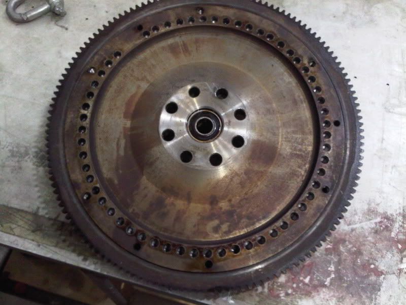
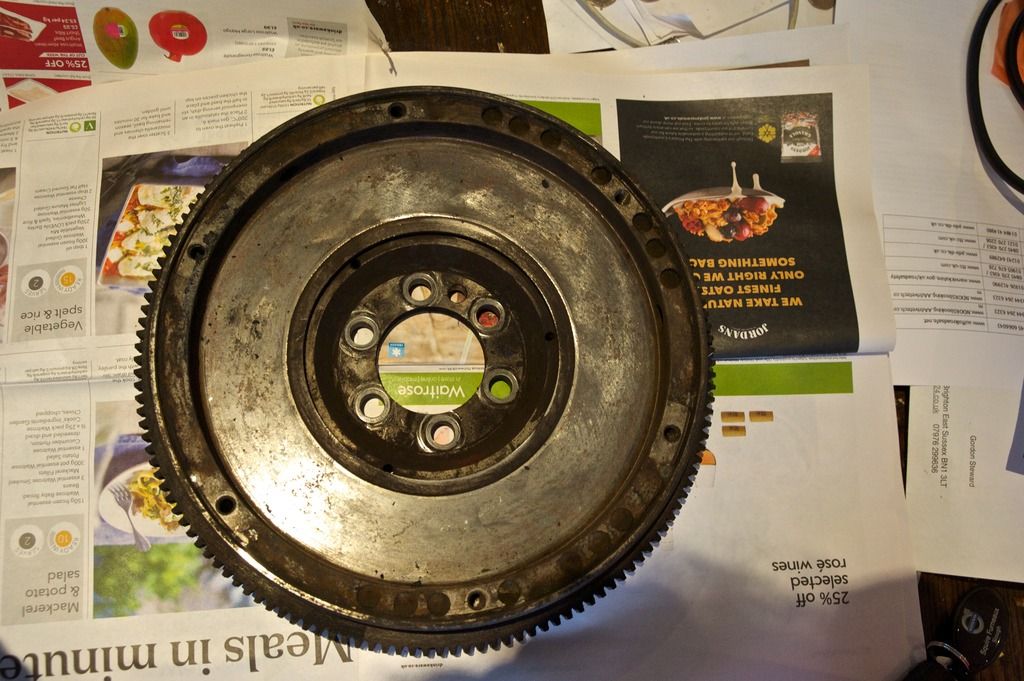
There are three holes at exact intervals on the flywheel edge, so no problem with the 36:2 pattern - but I wonder if the fact they go all the way through the edge will cause an issue?

Presumably, the sensor develops a magnetic field of finite depth (reach) and a hole deeper than said reach wouldn't have any adverse effect but an overly shallow hole may.
How deep all the holes can be may be limited by encroachment on holes for securing clutch cover plate.

flywheel%20W114%20edge_zpscdpzbn2i.jpg

Very careful advance planning of hole diameter and spacing required I think to avoid weakening clutch holes. Also, if a bolt is present where a void should be - then the signal input will be lost.
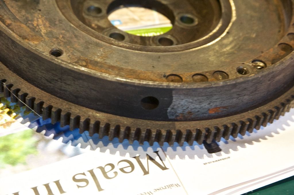
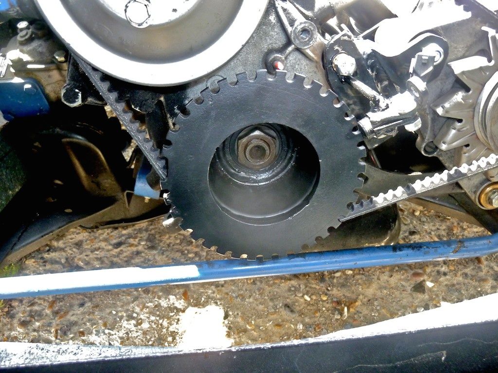
Presumably (again, as this is mere guesswork) the holes have to have sufficient diameter to present a clean 'cutting' edge. Contrast with straight 'cutting' edges of teeth. Until a drill bit appears that can drill a square hole, then circular holes they must be.... I would though, study the ideally formatted toothed wheel and crib the solid:space ratio as closely as possible.
 
Sound advice Bellow.

Pleasingly more searching found a trial drill hole through the bell housing of the SM to the flywheel below. Using my trusty tyre depth gauge I determined it was a depth in the drilled hole of exactly an inch (the mm section ran out) vs a depth to the flywheel of 22mm. So just under 4mm depth of drilling. Even more pleasant, that depth will not foul any of the bolt holes on the wheel.

The good thing is the flywheel is exposed below with no housing there in the way. I am not sticking my neck underneath any unsupported Citroen at full height for fear of the consequences but a ramp will reveal all.

SMflywheel_zps3df7enjy.jpg
 
This technical drawing of a 36.1 trigger wheel appears to delineate several " rules" for tooth / gap ratio on a magnetic pick up-- NB hall probe type might be different?? :dk: and doesn't address the issue of the shape of "tooth edge" unfortunately

quote

1--The sensor used (part number CRK-SEN5) has a 3mm
diameter magnetic pick up (inductive type 2 wire).
The diameter of your wheel if you are producing your own,
is controlled by the size of the magnetic pick up.
The gap between each tooth must be a minimum of 3.5 mm
and must not be less than the diameter (or width) of the magnetic pick up itself, otherwise the sensor will not be able to detect a gap, it will just see the teeth on either side.

2.The trigger teeth must have a minimum width of 3mm,
this is to ensure there is sufficient Ferous material present
for a suitable crank signal to be generated.

3. . It is recommended that you have a maximum gap between sensor and the timing wheel of 1mm.

http://www.sbdev.co.uk/Info_sheets/Crank_Sensors/36-1 Trigger wheel Setup Drawing-pdf.pdf


some more on dimensions here under pickups.
http://www.megamanual.com/ms2/
 
Last edited:
The question that instantly springs to mind from that paper is how do you determine when Cylinder 1 is at TDC?
 
Last edited:
I've found the answer.
 
My fault here :o for trying to shed some light on one specific design problem by quoting a particular example. That pdf figure refers to a 4 cylinder set up with presumably an adjustable timing wheel wrt to crank TDC and adjustable sensor position. In a 6 cylinder that angle would be 60 degrees of course and there would be only minor adjustment possible on the TDC/ missing tooth position wrt the sensor once the holes were drilled into the flywheel in your set up . Its a bit of a minefield getting into this stuff when there is no factory CPS! :doh:
 
A minefield indeed! The very good thing though is that I am being compelled to understand what I am doing from, if not first principles, certainly secondary ones. This is important as it is me that will be specifying the things that need to be done, and the even better thing is having techs (John and John but not Abz John) who have a lot ofexperience but neither have done a conversion ab initio. Then there is Billy who frankly should be studying electronic engineering, he is so bright (aspergers and other issues did him no favours in earlier life) although he'd probably make it all from transistors...

It's all rather fun, no doubt until nothing fires up!
 
Last edited:
Having wracked[ wrecked!] my brain thinking about this Charles for a couple of hours :wallbash: 
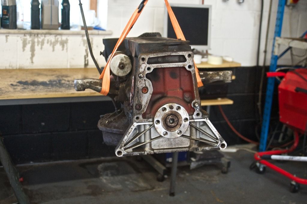
I am more and more drawn to the conclusion that the use of crank pulley mounted machined trigger wheel with suitable position sensor is the safest solution. Without the existing presence and position of a cps getting things positioned correctly and machining the flywheel is going to be fraught. :eek: I know you prefer the flywheel approach but without the input of someone who knows exactly what they are doing i.e. they have done this same or very similar engine before I foresee lots of potential pitfalls.:fail
At least with a crank pulley timing wheel its easily accessible and adjustable. Likewise with a suitable stout bracket the cps type sensor can be adjusted precisely.
Just saying.:dk:
 
Having seen that hole in the bell housing on the SM which is in the wrong place (it's a new hole and positioned opposite the sensor) I too am aware that it is not straightforward. My objections to a trigger wheel are less than they were - EDIS properly set up has a limp mode if it gets no CPS signal so it can still be driven, which was not the case with my BMW 02 which sensor failed 4 times (bracket and mounting issues) leaving me stranded. It was also not a rock steady signal as the engine moved a lot while the bracket didn't. A straight six should have less of an issue with engine vibration to the M10 4.

However, I am going to work my way through the theory and the issues as this is worth the effort also for the trigger wheel. The signal on the SM is strong and rock solid - even the retired SM specialist renowned for his conservatism was impressed by the idle.

Anyway I hope your brain recovers soon Graeme!
 
I begin to see where your aversion to trigger wheels came from Charles. Mounting the sensor "off engine" with the timing wheel "on the crank" is not good engineering practice.
With the sensor rigidly mounted on the engine block itself by a robust but finely adjustable bracket this should not be a problem. There was a picture on one of the engine conversions back in the early days of this thread- will try to find it.
Here's the one from the 280 sl thread. [Used the alternator bracket]

this was from the w114 v8 conversion [ used the sump casting ]
IMG_0714.JPG
 

Attachments

  • 280sl WHEEL.jpg
    280sl WHEEL.jpg
    72 KB · Views: 10
Last edited:
This was the set up on my Tii

trigger%20wheel%20TII_zps4qgm0kka.jpg


Coming back to the location of CP sensor I'm getting more confident that fitting it on the bell housing is entirely feasible. As can be seen below the flywheel has a fixed position on the crank

blockend_zpsxqo3ot5e.jpg


Note the six large and one smaller bolt holes on the above and on the flywheel below

flywheel%20W114_zpsvkbgzoly.jpg


With that variable out of the way, locate TDC and then with the sixty degree rule for CP sensor ahead of double tooth gap, one can determine the latter position by reference to where the sensor is most conveniently mounted, all of which can be bench derived with the engine out. I am going to study the mounting for the SM's CPS to see how that works.

I am not enamoured of either solution for the trigger wheels above! My sump doesn't protrude like the V8 and mounting on the alternator after my 2002 Tii experience not one I'd like to repeat.
 
Last edited:
Druk has just made a decisive intervention in favour of trigger wheels. If the flywheel has to be removed to make adjustments so will the gearbox and that costs money, whereas access to the trigger wheel is easier.

If it's going to hurt my wallet...
 
Druk has just made a decisive intervention in favour of trigger wheels. If the flywheel has to be removed to make adjustments so will the gearbox and that costs money, whereas access to the trigger wheel is easier.

If it's going to hurt my wallet...
Thats really what I was driving at with quote:- At least with a crank pulley timing wheel its easily accessible and adjustable.
;)
Although - on paper a flywheel set up would benefit from a larger radius wheel the accuracy of a drilled wheel would be very dependent on how accurately it was machined and you're are still left with that niggling curved edge trigger question.
Substitute an accurately manufactured timing wheel coupled to a suitable cps and you can be sure the tooth profile, tooth gap, missing tooth will all be spot on meaning accuracy and generated waveforms may in fact be better.
:thumb: 
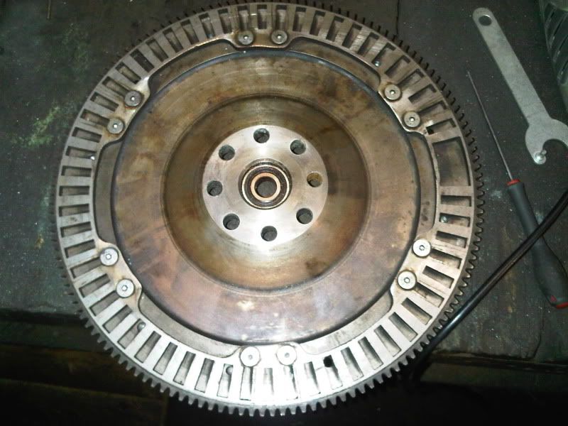
There was a comparison done on a Saab site where a guy machined the holes in a flywheel himself with a drill but later abandoned the idea in favour of a fabricated gap wheel with accurately machined slots.
IMG00001-20100716-1331.jpg

IMG00088-20100906-2047.jpg


thread is here
UKSaabs ? View topic - Fitting T5 to my C900
 
The curved edge is not an issue - my SM wheel is drilled that way, no problems at all. Machining would be done by a proper shop, not me with a Black and Decker.

Nard has done a video of an SM engine with non EDIS coil packs. Amusingly it is running a trigger wheel set up for the cams (and coil pack) and drilled flywheel for the CPS (44s onwards). You can see why I didn't want coil packs spoiling the engine look!

[YOUTUBE]e6fTLwj35T8[/YOUTUBE]
 
4-1Wheel.JPG


''If your using another style of tooth, e.g. 4-1 (1 tooth every 90deg with 1 missing) then you will need to fit the wheel so tooth 1 lines up with the sensor at around 60deg BTDC. A 4-1 would be minimum for a 4cy, a 6-1 wheel (tooth every 60deg with 1 missing) would be minimum for a 6cy,''

Can the number of teeth be reduced as per above? If so, then five peripherally mounted (on the flywheel) bolts with heads as teeth are all that is required - assuming space within the bell housing exists for them without encroaching on ring gear/starter pinion.
 
Explained here:- MegaSquirt-II Missing Tooth Trigger Wheel Decoder
Seems pretty complicated but it would appear that the latest software can make use of the extra teeth to more accurately predict the ignition point required. I imagine the demands on this goes up with RPM.
Quote:-
In later versions of the code (2.883+), the 'tach teeth' are still created for injection events, etc., but instead of the ignition timing advance signal being based entirely on the time after the last tach tooth (with intervening teeth ignored), the timing is set by the counting number of teeth, with only the amount between the last tooth and the desired timing estimated.
 

Users who are viewing this thread

Back
Top Bottom