grober
MB Master
dup
#
#
Follow along with the video below to see how to install our site as a web app on your home screen.
Note: This feature may not be available in some browsers.
oops see this was posred before by you Charles.

Analysing the SM there are sensors in the inlets (one immediately after the filter (MAP?) and one in each manifold - temp sensor),TPS, CPS, Lambda sensor, and coolant temperature sensor. I need to locate the latter two.
The aim is to start drawing up a spec for the MS conversion so that everything is thought through first.
More options to muse over....
Not forgetting to devise a method of accurately obtaining the 1mm air gap twixt flywheel and CPS (if the flywheel is chosen as 'trigger wheel').


 its more difficult to produce an accurate signal with VR sensors at low rpm than at high due to less signal for processing. Some examples here
VR sensors appear produce a native alternating current which varies in amplitude with rpm presumably a faster change in magnetic flux= more induced energy e.g.
You will be gratified to read Charles that larger wheels produce stronger signals.
ps HALL PROBE type sensors [ 3 wire] evidently generate more signal for processing and are for that reason thus favoured for Camshaft sensors being as how they rotate at half crankshaft speed
I took Bellow's comment to be more about devising a bracket that can supply the necessary gap accurately.
So we have
Sensors
Sensor locations
Mounting location and bracket for CPS
Mountings for other sensors
Location for coil packs and module
Location for MS
Type of MS
Injector spec
Rail design
Fuel pump
Fuel pressure regulation
Map for fuelling
Map for ignition
Loom
Other musings - limp home mode for sensor loss?
(all of this will be considerably easier with an engine back!)
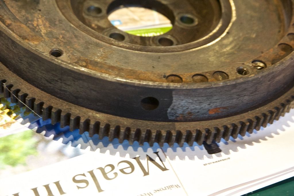
My flywheel face - too many holes irregularly drilled (for balance I think).
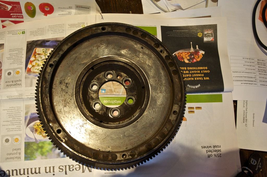
...and looking at the above, that depth is not a great amount - but must mimic the open holes behaviour w.r.t magnetic flux. The slot to mimic the missing tooth (as it needs to be cut) will be approx 3.6'' minus the hole diameter - an awkward sod of a machining job and, depending on where it has to be located, may make rebalancing impossible (if material to be removed diametrically opposite coincides with a clutch cover plate bolt). Ascertaining the position of the locating dowel (the seventh hole) w.r.t. TDC will give a clue to the above.
If any of the above is insurmountable, then it's back to a crank nose mounted wheel as triggering method. There is still (I think) a method to get the flywheel to act as trigger (without incurring the problems I have associated with drilled holes.....)
Coil pack under the battery tray - inspired!
...and looking at the above, that depth is not a great amount - but must mimic the open holes behaviour w.r.t magnetic flux. The slot to mimic the missing tooth (as it needs to be cut) will be approx 3.6'' minus the hole diameter - an awkward sod of a machining job and, depending on where it has to be located, may make rebalancing impossible (if material to be removed diametrically opposite coincides with a clutch cover plate bolt). Ascertaining the position of the locating dowel (the seventh hole) w.r.t. TDC will give a clue to the above.
If any of the above is insurmountable, then it's back to a crank nose mounted wheel as triggering method. There is still (I think) a method to get the flywheel to act as trigger (without incurring the problems I have associated with drilled holes.....)
We use essential cookies to make this site work, and optional cookies to enhance your experience.