• The Forums are now open to new registrations, adverts are also being de-tuned.

Mercedes W114 250 Coupe - help!

Having all important bits in my hall (I'll look at the gearbox bell housing tomorrow) it would appear that the flywheel has good clearance from the sides of the engine rear plate (or whatever this should be called), and I imagine given the bell housing bolts in to this, I would estimate a good 1 - 1.25 cm clearance.

So, absent other factors, some protrusions might well work.

housing2_zpsibcmyqe4.jpg


flywheel%20in%20housing2_zps0ymcrqbj.jpg


flywheel%20in%20housing_zpsoawxphvs.jpg
 
I have done some measuring of the flywheel and think that with spacing evenly it should be entirely possible to drill a 5mm hole and not come close to fouling the bolt holes in any meaningful way, but it does bother me slightly.

Whatever depth is chosen it will have to consistent (at least diametrically) to preserve balance - or very cunningly varied to provide the balance correction for the slot....

Would protruding screw heads work instead of holes? Drilled and tapped into the face behind the ring gear with an adequate gap left for triggering. They couldn't be higher than the bottom of the ring gear teeth or the started dog would foul but that might be enough?

Hex headed bolts are what I envisaged. Neatly (I think) they can straddle the peripheral holes and the clutch cover ones also. Thoughtfully torqued, they can provide straight (at 90deg to rotation) leading and trailing edges to the CPS and rebalancing the crank more easily achievable. M6 with 10mm hex heads say?


Those balancing holes are a lot deeper than I hitherto realised.
 
Those balancing holes are a lot deeper than I hitherto realised.

About 4mm vs the non toothed width of about 2.5 cm on the flywheel. If the drilling is centred they won't impede at all.
 
I can't say that I think adding bolts will do anything fundamental to help. I can't visualise any real benefit for the three obvious disadvantages - it adds another stage of precision, namely that the orientation of each hole has to be exact, the sensor mount will be the same, the holes drilled to fit will be deeper than the 5 mm required for the plain drilled holes (so fouling of the three existing holes and the 6 clutch bolt holes will be more likely).
 
Last edited:
Precision: no more than required for holes as trigger edges and can (if preferred) be drilled right through - removing an awkward 'stop at 5mm deep' drilling operation which has enormous implications re balance. The spacing (not being dictated by the existing three holes) can be orientated to straddle all clutch cover bolts avoiding any possible interference. (Incidentally I have peripheral mounting in mind here). On completion the balance is out by the weight of one small bolt head - contrast that with a 3'' slot 5mm deep as wide as the diameter of one of those existing three holes. Chances are that imbalance can be recovered by using a shorter bolt on the diametrically opposite side vs longer elsewhere (in any case it is an easy calculation to compare the mass of a bolt head with the required length of bolt thread to compensate).
It requires the holes be tapped, but there will be fewer drilling stages for smaller holes.

I'm interested to see Druk comment further (as he has some (similarish) angle on this).
 
Last edited:
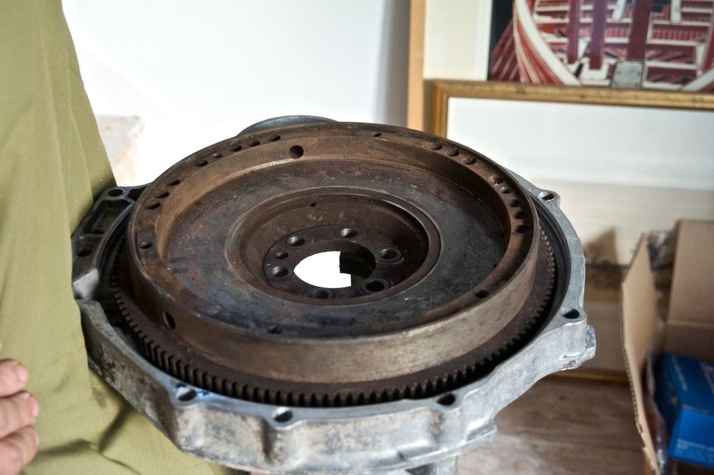
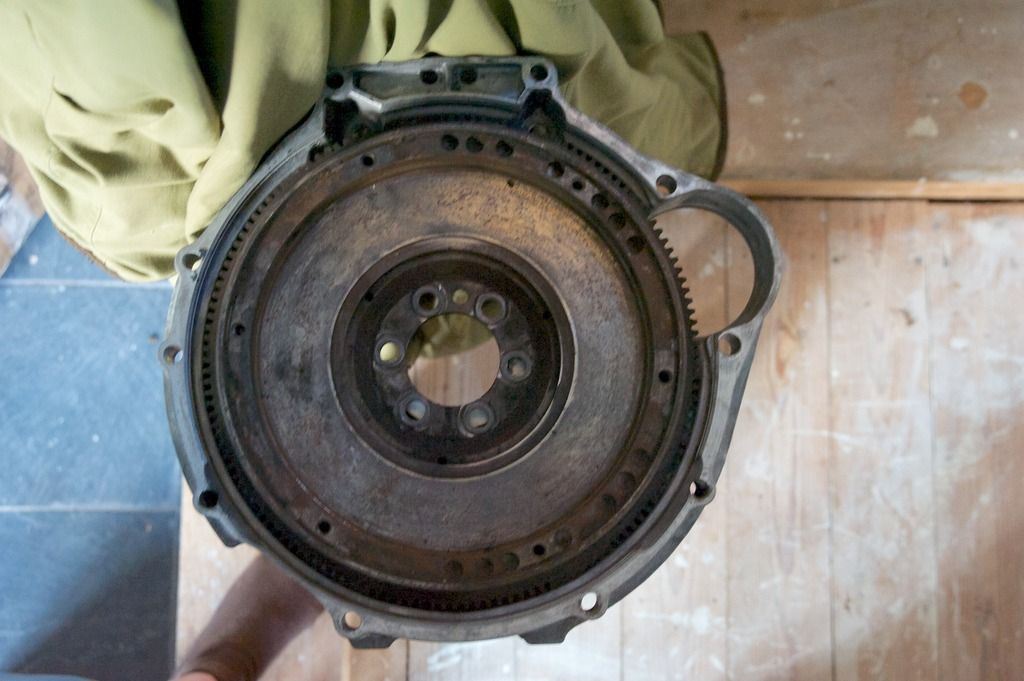
The beautifully simple thing about the drilled solution is that the 3.5mm VR sensor will always be an exact distance from the un-drilled surface of the flywheel, to all intents and purposes, parallel. Add a flat nut to that equation vs the curvature of flywheel and the sensor to nut relationship will be variable. If the hole for the first solution isn't drilled at an exact angle it doesn't really matter as the depth of hole will not really be an issue, whereas any imprecision in the angle of the drill hole to the nut will add an angle to the surface of the nut, further exaggerating that lack of parallel surfaces. Having just experimented with a 5 pence piece (the closest to a nut without a shaft I could find), there is about 1mm difference at the edges to centre height. That's a lot of variability in pick up each rev cycle.

I'm not sure I agree about the additional balancing being required as 3" - the difference in balance one side to the other is a 10mm wide hole undrilled to a width of 5mm.

Having measured the location of the clutch bolt holes, the depth of metal remaining on the outer perimeter when drilled to 5mm would still be greater than the depth of metal from the hole to the inner edge. I don't think this is a problem compared to ensuring deeper drilled holes exactly miss either the three through holes or the clutch bolt holes, given you have to distribute both sets of holes evenly around the surface anyway.
 
Last edited:
All valid and well thought out points CM.
I'll add a suggestion (to ease balancing) later.
 
it adds another stage of precision, namely that the orientation of each hole has to be exact

Precision is the easy bit. Flywheel mounted in lathe and a very slight groove skimmed round the periphery would give an accurate track for drilling. A simple jig would give spacing.

Precision: no more than required for holes as trigger edges and can (if preferred) be drilled right through - removing an awkward 'stop at 5mm deep' drilling operation which has enormous implications re balance. The spacing (not being dictated by the existing three holes) can be orientated to straddle all clutch cover bolts avoiding any possible interference. (Incidentally I have peripheral mounting in mind here). On completion the balance is out by the weight of one small bolt head - contrast that with a 3'' slot 5mm deep as wide as the diameter of one of those existing three holes. Chances are that imbalance can be recovered by using a shorter bolt on the diametrically opposite side vs longer elsewhere (in any case it is an easy calculation to compare the mass of a bolt head with the required length of bolt thread to compensate).
It requires the holes be tapped, but there will be fewer drilling stages for smaller holes.

I'm interested to see Druk comment further (as he has some (similarish) angle on this).

I'm thinking cheese head screws. Almost same height above base datum but much less mass than hex heads so less imbalance if error occurs. Cap screws might work if the sensor didn't 'see' the allen hole.


.
 
Last edited:
What's the clearance on the other side of the wheel nearest the engine? What's that face like---PICCY??? Could holes be drilled on that face at the periphery without interference ? Or is there clearance on the face or slightly recessed for a slotted timing wheel ---like the alfa V6 Is it possible to position a CPS to look at such a surface?
28ard43.jpg

2n6aixk.jpg
 
What's that face like---PICCY???

Your wish

flywheel%20rear_zpsdkj7xwn9.jpg


A very interesting suggestion. There is clearly space behind as you can see the wheel is concave and so in theory something could be mounted. A sensor could be mounted along the engine housing and sense through it, but the option of doing it from the side would be difficult because the construction of the housing is very strong and thick on the sides. How one might mount the ring on that surface is a challenge.

Just back from Bicester. Lots of progress to report with photos, which I'll process this evening, but the SM flywheel is drilled much deeper than I thought - 9 mm to the base of the drill hole and I think that is just not going to work with any of the clutch mounting bolt holes.

Time for plan B.
 
but the SM flywheel is drilled much deeper than I thought - 9 mm to the base of the drill hole

Ain't seen a trigger wheel with 9mm teeth....
Is the CPS permanently magnetic? If so, some experimentation with iron filings to ascertain the reach of its magnetic field may offer up an answer as to how deep the holes need be.

Time for plan B.

Do tell!!
 
Ain't seen a trigger wheel with 9mm teeth....
Is the CPS permanently magnetic? If so, some experimentation with iron filings to ascertain the reach of its magnetic field may offer up an answer as to how deep the holes need be.

I didn't take a photo but the hole was the shape of the drill bit - a small hole at the base (the guys thought that was the original drill hole), a 4mm straight edge from the top then an angle down to the centre of the hole.

I shall do some more research. I wonder how the flat holes on the wheel pictured earlier on were drilled? Time for a chat with a machine shop.
 
I think plan B proper is Graeme's splendid suggestion of a trigger wheel. Plenty of space on the back to fit a variety of trigger wheels, the only drilling required would be 4 holes on the wheel, which would have a rock solid anchor and plenty of positions on the engine housing to fit the sensor.

It is simple and quick. I like it!

4 or more holes through the wheel with perhaps concentric flats of a slightly wider diameter vertically machined/drilled around them on the flywheel sloping side . This would permit the installation of 4 or more small pillars or spacers on a flat rather than sloping surface and in turn to present a flat series of spacers/pillars to mount the trigger wheel on and adjust its height wrt the flywheel "deck" :dk: 
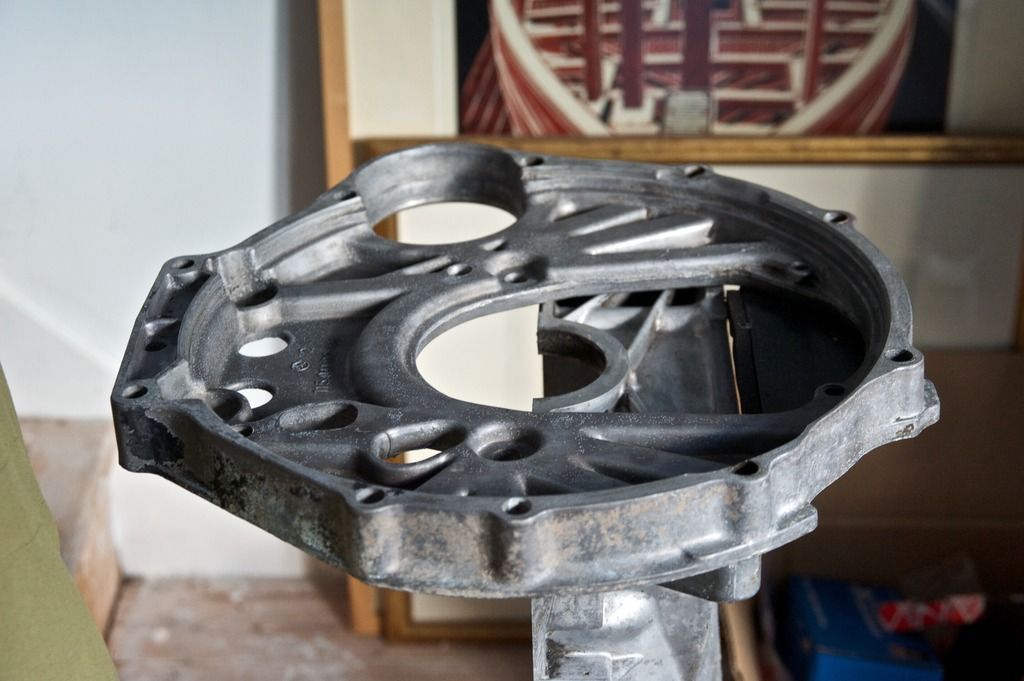
. The diameter of the slotted section of the trigger wheel chosen to co-inside with the position of the sensor mounted on the engine backplate/housing. The sensor to be mounted axially in a similar orientation to the starter motor is how I visualise such a setup altho you may have to get a wheel of the right dimensions individually cut? :dk:
 
A perfect description Graeme. I think the commercially available trigger wheel sizes should be fine, I shall ask them the teeth depth to make sure.
 
The most likely area is that black plate at the base. The sensor bracket can be screwed in to the base of the casting underneath the crank and a hole for the sensor to go through drilled in the black plate through to the wheel. The plate itself is slightly too thin to act as a primary mounting plate.

Looking again at the back of the flywheel, after the mound in the centre it goes flat for about 10 cm where a trigger wheel can be mounted.

It's all looking too easy. There will be a catch, there has to be.
 

Users who are viewing this thread

Back
Top Bottom