• The Forums are now open to new registrations, adverts are also being de-tuned.

Mercedes W114 250 Coupe - help!

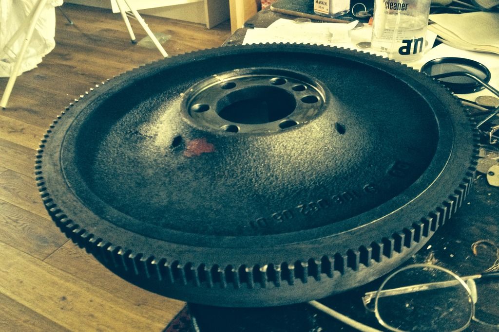
G (if I understand correctly) proposes a trigger wheel mounted at its inner diameter and with its teeth at its outer. The converse is also possible. Dare you drill the outer edge of the flywheel (where the ring gear mates to it)?

flywheel%20rear_zpsdkj7xwn9.jpg
 
Gosh, that's food for thought. Nothing there to interfere with a pattern as on the other side.

Perhaps even the ring gear? It's a bit wider there.

I'll do some measuring in the morning.
 
I wouldn't look to drill into the ring gear or that part of the flywheel in isolation (weakening potential too high) but possibly both together such that the tapped thread is carried equally by both with the join line between the ring gear and the flywheel being a guide for centring the drilling on.
Braver still - drill 35 holes there and forget fixing a separate wheel....

edit PS.
Ignore last suggestion - the machined 'slot' too risky.
35 tapped holes and 35 hex headed bolts?
 
Last edited:
A 3ltr turbo diesel :devil:

That's as old as my Trilby.

Billy would like to use the car as a test bed for retro fitting an electric engine and battery pack. I demurred having spent way too much time researching electronic ignition and crank position sensors.
 
Sensors
Sensor locations
Mounting location and bracket for CPS
Mountings for other sensors
Location for coil packs and module
Location for MS
Type of MS
Injector spec
Rail design
Fuel pump
Fuel pressure regulation
Map for fuelling
Map for ignition
Loom

Other musings - limp home mode for sensor loss?

Sensors

TPS
CPS
MAP
Coolant temperature
Inlet air temperature
Idle control valve (the rubber house had split and fallen off of the SM one - out of a Vauxhall Astra!)
Wideband lambda
 
Very pleasing - the flat part of the rear of the flywheel is almost 2 inches wide and is located exactly where the inspection plate covers it. Two or even three available trigger wheels will fit in that space.

The ring gear and flywheel edge look unsuitable - too narrow and you'd be drilling at the join of the ring gear and flywheel and the ring gear is also very narrow.

Less pleasing, the base of the sump is not that substantial so some imagination will be needed for the bracket. I think this looks the best option now.
 
I'm thinking cheese head screws. Almost same height above base datum but much less mass than hex heads so less imbalance if error occurs. Cap screws might work if the sensor didn't 'see' the allen hole.

Aologies Druk - I as good as asked you a question directly then ignored your reply.
Bolts for me as I could more easily tighten them (the thought of even one coming loose....) but agreed, they(screws) would better fit the 'circularity' concern. I'll bet the CPS would 'see' the hole in a cap head!
Bolts may be back on the agenda though axially mounted this time. Any thoughts on placing them (either a sufficient amount to secure a trigger wheel or a full 35 of them) between the ring gear and the outer rim of the flywheel?
 
The ring gear and flywheel edge look unsuitable - too narrow and you'd be drilling at the join of the ring gear and flywheel and the ring gear is also very narrow.
.

There is considerable stress in the ring gear due to it being shrunk on with heat. Encroaching on it rather than drilling a whole hole in it is as far as I'd dare.

Very pleasing - the flat part of the rear of the flywheel is almost 2 inches wide and is located exactly where the inspection plate covers it. Two or even three available trigger wheels will fit in that space.

Bear in mind the area under discussion is the reverse side of the clutch rubbing/friction surface. Consequently, it can be expected to get very hot on occasions. Shouldn't be a problem but if locking nuts or compound has to be employed it will have to be capable of resisting the temperature.

Another option would be to braze a wheel (its inner diameter to the tapered part of the flywheel emanating radially from the hub). I assume the flywheel is formed of cast iron (which brazes very well without the inherent dangers of welding) and the three (axial) holes near the hub would accept a temporary jig to locate it during brazing. (Or accept permanent 'drive lugs' with the disc merely tack brazed to restrain it axially).
 
Good progress on welding in the last few days. Lousy iPhone photos from today, good quality ones from Wednesday.

The o/s bulkhead with plate in the rotted area of air intake water trap visible.

bulkheadstrip_zpsvojq0ebp.jpg


Friday - plate nicely welded in

bulkheadstrip2_zpscnyf4snq.jpg


o/s Inner wing revealing its rust bits as it was stripped

innerwing_zpstnzuzopt.jpg


Plates now spot welded on today for finishing

innerwing2_zps2fjsdf1d.jpg


O/s rear inner wheelarch rust cut out and plates shaped

reararchplate_zpsbirg7tyg.jpg


Spot welded on today

reararchplate2_zpsu56i2crp.jpg


I took Tony up on Wednesday in the SM (which being an ex Citroen mechanic he loved) to see progress and to have a tour. He really loved it - Bramble the cocker and Chester the collie, a real mix of cars in Simeon's and at the body shop (he especially loved the Jensen with the LS3 Corvette engine as he looked after his daughters V8 Griffith for some years when she raced it), and he thought they were doing a smashing job.
 
John, the tech with experience of an Omex installation (who is now researching MS to fit to the BMW 3.0 CSL I mentioned) thought that my proposed location for the trigger wheel should be fine - as he put it, I'm pretty unlikely to be doing launch control type starts or race in the vehicle. He thought an auto would be better though. Another thought to put in my pipe.

Dan at the body shop confirmed that Matt with the broken leg would likely be off for up to 6 weeks. Which with their current workload is likely to push my car back 6 weeks too. Simeon is happy though to crack on with things like suspension replacement etc and much of the engine work and sensor fitting can be done on the bench. Still a bit of a bore. Happens though with small businesses.
 
Last edited:
Some nice fitting there Charles, takes a fair bit of skill does that....
 
A couple more from Tuesday. The section through the front bulkhead where the heaviest rust was and the drain holes that were the cause of it all. You can see the fabrication of the bottom third of the heater fan mount - a full circle must be fun to fabricate! What I like to see is that the bulkhead work, 95% of which will be invisible when the new heat shield is put in place has been finished so nicely. I like that.

bulkhead3_zpsfhyxkcac.jpg


The new rear bumper hanger bolt

rearbumperhanger_zpsmpofwzmi.jpg
 
Last edited:
In philosophical terms the car's bulkhead is the complex physical manifestation of the man/machine interface. Its where all the driver inputs [ switches steering brakes clutch accelerator] and feed back [steering, instruments]takes place.:cool::cool:
Its just a pity that its often the worst place for rust. :wallbash:
 
In this car it's the complex physical manifestation of the effects of blocked drain holes, water and oxygen upon poorly rust-proofed steel!

All the seams will be seam sealed, and the internal void will be heavily waxed to ensure this doesn't happen again!
 
I had a look at the battery tray in the car, which would indeed be ideal for mounting the coil packs. However, it is a good 20 cm further away from the spark plugs than the original dizzy location. A question to the technical gurus - would longer plug leads to overcome this cause any timing or other issue?
 
I had a look at the battery tray in the car, which would indeed be ideal for mounting the coil packs. However, it is a good 20 cm further away from the spark plugs than the original dizzy location. A question to the technical gurus - would longer plug leads to overcome this cause any timing or other issue?

Well, I did once have an engine that in its handbook the timing (fractions of an inch BTDC) was given for a specified length of lead! Why, given electricity moves so fast - I have no idea.

Bigger concern (for me) is - do they have to be kept in pairs away from each other or is the cross firing theory mere bunkum?
 
Of your second sentence, I have no idea as to the answer! But the coil pack itself is firing two cylinders on a wasted spark basis simultaneously.
 
Two firing simultaneously can sit together. Pairs together?... I'll try and separate them when I (finally) get around to checking the dizzy.
Talking of which, in the quest for authenticity, presumably an attempt will be made to route the leads from the cap in the correct firing order? What is the firing order? And which plugs are paired (via coils)?
 

Users who are viewing this thread

Back
Top Bottom