Testing the MAF for dummies

Page may contain affiliate links. Please see terms for details.

SimonsMerc

MB Enthusiast
Joined
Oct 3, 2004
Messages
1,147
Location
Sudbury, West London
Car
Merc S212 E350 CDI BlueEfficiency Sport 256bhp, Suzuki GSX-650F, Mitsubishi Outlander PHEV Dynamic
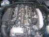
Ok, so a couple of people have posted the numbers from their MAF and say that they got them by using a voltmeter and...erm...well. Ok, where the hell is a MAF in an E320CDI? What does it look like? Got a photo? Which connector do I pull out and where do I measure the voltages? Under what conditions?

In short, does someone want to write a simple howto with photos so that I can test my MAF? :)

Thanks,

-simon
 
Very briefly for now.

The MAF is the first electrical component just after the air filter. It will have a flat five pin connector, only four pins are used though, connections
2=12v, 3=Gnd, 4=5Vref, 5=output.

Meter the output with respect to Gnd. The car body is Gnd.

You may find it easier to trace the wires back to the ECU and meter the connector once you have unscrewed the back of it.

Run the engine and take readings from idle up to 5000 rpm, in both neutural and full load conditions.

The values will range between a low of 1v and upto 4.5v ish. The values may well not be the same as others have reported because your MAF is a digital output not an analoge one. This is due to yours being made by Pieburg and most others by Bosch.

You will probably find the MAF is working ok as the Pierburg ones are sooo much more reliable.
If it's faulty first give it a clean with some carburettor cleaner or buy a new one. They are about £44 from the dealer, alternatively there is a new one on ebay at present.
 
Right, I'm dumb. I mean, this "for dummies" guide? It's got to be able to handle real dummies like me!
Dieselman said:
The MAF is the first electrical component just after the air filter. It will have a flat five pin connector, only four pins are used though, connections
2=12v, 3=Gnd, 4=5Vref, 5=output.
Ok, fine. I can do that. If I could find the bloody thing! I must be really dense...does anyone have a photo where they could put a big red circle and a big red arrow saying "click here"?
Dieselman said:
Run the engine and take readings from idle up to 5000 rpm, in both neutural and full load conditions.
Ok, I can do that - assuming all I need to do for the neutral setup is get the wife to sit in the drivers seat and hit the accelerator to get and sustain enough rpm, right?
As for full load...hrm. Should I pull some cables from the engine into the car and actually test it while driving (or rather while the wife is driving?). Or did you mean something else?
Dieselman said:
You will probably find the MAF is working ok as the Pierburg ones are sooo much more reliable.
This is very encouraging - thanks :)

-simon
 
Dieselman said:
Very briefly for now.


The values will range between a low of 1v and upto 4.5v ish. The values may well not be the same as others have reported because your MAF is a digital output not an analoge one. This is due to yours being made by Pieburg and most others by Bosch.

.

If its digital output, surely you cannot measure it with a normal meter?
 
Hi,

As far as I know, both Pierburg and Bosch hot film and hot wire air mass sensors have analogue outputs. The digital sensors that come to mind are the KV type air flow meter (Mitsubishi) some Ford MAP sensors.


To test MAF sensors with a multimeter is a wast of time imo. Only an oscilloscope will show the voltage over time. In theory a 'worn' MAF sensor could still get to it's top voltage, but could take a lot longer. Most air mass sensors get to their top voltage before maximum air flow is reached. The ECU uses the other load sensors like throttle pedal position sensor to fill in the rest. This means that although the sensor gets to max. voltage, it could still be reading a lower voltage than nessesary for any given air mass.

regards,

job
 
DrNick said:
If its digital output, surely you cannot measure it with a normal meter?

Appologies the output is an analogue signal that has been through a digital conversion.
The DMM will see a standard analogue output.

If viewed using an ossiloscope the results show a chopped output.

Quote:
Secondly the CDI output signal is clearly made by a digital to analog converter. Notice the steps in the signal. So most likely the analog signal from the actual sensor element is digitalized, maybe digitally trimmed to get the calibration right, and after that converted to an analog signal again
 
jgevers said:
Hi,

As far as I know, both Pierburg and Bosch hot film and hot wire air mass sensors have analogue outputs. The digital sensors that come to mind are the KV type air flow meter (Mitsubishi) some Ford MAP sensors.


To test MAF sensors with a multimeter is a wast of time imo. Only an oscilloscope will show the voltage over time. In theory a 'worn' MAF sensor could still get to it's top voltage, but could take a lot longer. Most air mass sensors get to their top voltage before maximum air flow is reached. The ECU uses the other load sensors like throttle pedal position sensor to fill in the rest. This means that although the sensor gets to max. voltage, it could still be reading a lower voltage than nessesary for any given air mass.

regards,

job

You are correct re the output being analogue but it has been processed through a digital amplifier.

With an analogue MAF there is no reason why a DMM can't be used as long as the airflow is kept constant for a short period. If the vehicle is being driven in a high gear this will result anyway.
The no load tests simply require the revs to be held constant at each stage whilst a reading is taken.
These are not "scientific" tests carried out using a WOT rev on a rolling road, so timebase is not measured but isn't required. Don't forget so far all these results are for diesel engined vehicles so WOT doesn't apply.

MB dealers only test MAF outputs at idle anyway.

Obviously it would be more scientific to test the MAF in a given airflow condition, but if a comparison is drawn betwen similar engines at steady revs and load conditions, that will act as a reasonable guide.

These tests started as a comparison with known good and bad MAF sensors and so far appear to be an accurate method of determining a poor performing sensor.
I understand your thoughts regarding the sensor heating upto it's potential, but that is the problem anyway, the sensor plate is being insulated from cooling down hence the output is reduced.
The easier it is for a MAF to maintain heat the lower the air mass and so the output is lower.

Anyway, thanks for your input and feel free to disagree.

Regards
 
Hi Dieselman,

IMO it is not correct to test a MAF with a DMM only. A faulty MAF can still read correct voltage at idle. Quite often they read higher. The faulty MAF can also still perform over it's complete voltage range. Very often I see MAFs that still get to their maximum voltage but if you check the live data during running it is performing like a faulty MAF.

The reason for this is (a bit of basic software operating strategy):

Let's say a TD engine requires 1500 KG/h at 4000rpm and full load. If the air mass sensor is working correctly it will get to it's maximum output voltage at 800 KG/h. The fuelling and boost control for the additional 700 KG/h is calculated by the ECU using the other sensors like throttle pedal position sensor etc.
This means that a faulty MAF sensor can still get to it's maximum voltage but this might not happen until it gets to 1500 KG/h. (the KG/h figures I have used are just to show the strategy)
Another reason for not using a DMM is that the voltage progression is not linear. Even an oscilloscope is not a definate way of diagnosing a faulty MAF.
The live data on the scan tool will give a much better idea of actual airflow measurement. But remember that there are several other reasons why an MAF could read low like a blocked exhaust or leaking EGR valve.

One way to prove this theory is to plug your scan tool in and look at air mass live data. When accelerating with full throttle from standstill, the airmass will show something like 1250 KG/h (depending what type of engine) more or less straight away. It will keep showing this figure right to 4000 revs in all gears. Yet in reality the air requirement for an engine keeps going up the higher the load and engine speed.

So yes, I disagree. By the way, the reason why I disagree is not just because of what I find in practice, but I have also been trained by the people who designed and make these diesel and petrol injection systems.

regards,

Job
 
jgevers said:
Hi Dieselman,

IMO it is not correct to test a MAF with a DMM only. A faulty MAF can still read correct voltage at idle. Quite often they read higher. The faulty MAF can also still perform over it's complete voltage range. Very often I see MAFs that still get to their maximum voltage but if you check the live data during running it is performing like a faulty MAF.

The reason for this is (a bit of basic software operating strategy):

Let's say a TD engine requires 1500 KG/h at 4000rpm and full load. If the air mass sensor is working correctly it will get to it's maximum output voltage at 800 KG/h. The fuelling and boost control for the additional 700 KG/h is calculated by the ECU using the other sensors like throttle pedal position sensor etc.
This means that a faulty MAF sensor can still get to it's maximum voltage but this might not happen until it gets to 1500 KG/h. (the KG/h figures I have used are just to show the strategy)
Another reason for not using a DMM is that the voltage progression is not linear. Even an oscilloscope is not a definate way of diagnosing a faulty MAF.
The live data on the scan tool will give a much better idea of actual airflow measurement. But remember that there are several other reasons why an MAF could read low like a blocked exhaust or leaking EGR valve.

One way to prove this theory is to plug your scan tool in and look at air mass live data. When accelerating with full throttle from standstill, the airmass will show something like 1250 KG/h (depending what type of engine) more or less straight away. It will keep showing this figure right to 4000 revs in all gears. Yet in reality the air requirement for an engine keeps going up the higher the load and engine speed.

So yes, I disagree. By the way, the reason why I disagree is not just because of what I find in practice, but I have also been trained by the people who designed and make these diesel and petrol injection systems.

regards,

Job

I believe what you are saying is that the ECU adjusts the MAF output measured, this is true but it can't actually adjust the output voltage of the MAF, although admittedly we may not be seeing this alone.
Figures very similar to ones achieved will be found if a MAF is bench tested with a 12v and 5v supply and an variable measured air flow.

I am aware of the requirement to run under load and view the MAF output charecteristics against theoretical values, but we don't have that equipment available and have so far found using a DMM to be a good indicator.

Assuming Dr Nicks EGR valve to not be leaking (which obviously would reduce intake consumption), and his Cat not to be blocked, (which surely would reduce the terminal revs of his engine which they are not), given the readings he has posted for his MAF do you think he should replace it or not?

It would be interesting to take more readings with no other changes than a new MAF installed as a comparison.
 
Absolutely. Whatever verbal diarhoea I spout here, in the workshop, if a CDi comes in with low power, I rev it once to see how it boosts and then fit a MAF sensor. 99 out of 100 times it is right. This provide a much quicker turn around.

regards,

Job
 
How much air would an EGR valve be capable of leaking? I always thought that the amount of gas being recirculated was quite small?
Is this an easy thing to check as well? I may as well be fully armed with info for this weekend.

Nick
 
DrNick said:
How much air would an EGR valve be capable of leaking? I always thought that the amount of gas being recirculated was quite small?
Is this an easy thing to check as well? I may as well be fully armed with info for this weekend.

Nick

Normally it is but it can be upto about 20%??? in idle conditions

There is a hefty spring pushing the EGR valve closed. To properly check you need the inlet manifold or at least the air duct leading to it, but if you apply vacuum (suck) on the EGR modulator pipe you will retract the valve plunger. When you release the vac. you will hear the valve thud against the seat.
Unless the spring is broken I doubt it's the EGR valve. Normally you can tell due to the amount of black smoke when coming off idle onto power. If there is too much EGR the oxygen level is depleted so the mixture becomes too rich due to the increase in fuel delivery.

Also if you meter the MAF at idle and manually operate the EGR valve you should see the MAF output vary as all other conditions will remain constant.

IIRC. Also if you manually operate the EGR valve at idle you will hear the engine note change as the exhaust returns and the oxygen level alters.

Ps
If you have a knackerd MAF you can sometimes block the EGR vac pipe without the ECU throwing limp home, if the MAF is good then the ECU will definately trip limp home mode.

I've just donned my flameproof suit. ;)
 
Last edited:
Not as easy to check properly. I normally use the diagnostic computer to activate the EGR valve. At the same time I monitor the MAF sensor.
With EGR closed I would expect something like 420 kg/h with EGR 100% open probably 250 KG/h.

A manual method would be to apply vacuum to the valve to open it and watching the MAF voltage reduce. If you don't have a Mityvac pump for producing vacuum, the easiest way would be to by-pass the EGR solenoid and put vacuum from the pump on the valve directly.

Hope this helps.

regards,

Job

I see I have just repeated what Dieselman said. I got interupted while typing.
 
Last edited:
Dieselman said:
The MAF is the first electrical component just after the air filter. It will have a flat five pin connector, only four pins are used though, connections
2=12v, 3=Gnd, 4=5Vref, 5=output.

Meter the output with respect to Gnd. The car body is Gnd.

You may find it easier to trace the wires back to the ECU and meter the connector once you have unscrewed the back of it.

Run the engine and take readings from idle up to 5000 rpm, in both neutural and full load conditions.

The values will range between a low of 1v and upto 4.5v ish.

Hiyas,

Well I finally bit the bullet in my quest to work out why the hell my car is averaging 28 miles per gallon, and decided to test the MAF sensor. Will tell this story in a couple of posts, with a photo in each so I can talk around them. First of all, here is my engine in all its glory - isn't it nice? :)
 

Attachments

  • lump.jpg
    lump.jpg
    63.6 KB · Views: 307
Now, here is what I think the MAF sensor is. Let me know if I'm wrong :p
 
So, opening up the MAF, this is what I see - I'm counting pins from the right as there are little numbers on the connector.
 
So, I start the engine, connect one end of a multimeter to ground, the other end to each of the pins in turn...and nothing. A reading of 0 volts from each and every pin when the engine is on and idle. What the hell am I doing wrong?! :)

Does the connector actually need to be plugged in while measuring? This wouldn't make sense in my limited understanding of electricity, but I guess it's possible. If so how do I measure, pull some wires out somewhere?

I didn't get a chance to measure the bits under load (wife wouldn't come outside to hit the damn accelerator!), is it even worth trying if I'm getting 0v from any of the pins at idle?

I did try going for a drive with the MAF sensor disconnected (like on the above photo), and there was a very clear difference between "normal" driving and without the MAF.

Any ideas? Am I doing the right thing, if you look at the photos am I identifying the right component? :)

Cheers for any help you can offer,

-simon
 
Yes you have the correct bit, and yes you have to measure with the plug connected, as the plug is providing power to the sensor. Disconnect the plug and the sensor is no longer powered! 0 volts is the result.
Its encouraging that unplugging it makes a difference - it can't be completely stuffed, although mine just read low at higher rpm.

You can measure by poking the multimeter probes into the connector to make contact with the metal deep in the connector. It requires a bit of perseverence to make sure you have a good connection. You can use some bare metal part of the bodywork as a ground reference, so yu only have to poke one of the probes into the connector.
 
DrNick said:
Yes you have the correct bit, and yes you have to measure with the plug connected, as the plug is providing power to the sensor. Disconnect the plug and the sensor is no longer powered! 0 volts is the result.
Its encouraging that unplugging it makes a difference - it can't be completely stuffed, although mine just read low at higher rpm.

You can measure by poking the multimeter probes into the connector to make contact with the metal deep in the connector. It requires a bit of perseverence to make sure you have a good connection. You can use some bare metal part of the bodywork as a ground reference, so yu only have to poke one of the probes into the connector.

Ooooh, right, so basically those cables are incoming power and ground, outgoing 5v reference and outgoing reading. And I'm just stupid for not thinking about it when Dieselman wrote exactly that in a few posts earlier. :)

Will test it properly tomorrow - cheers!

-simon
 

Users who are viewing this thread

Back
Top Bottom