W215 cl500 abc hydraulic system repair

Page may contain affiliate links. Please see terms for details.

crownhouse

New Member
Joined
Jun 30, 2009
Messages
27
Location
Oxford UK
Car
W215 W140 and W115
A W215 CL500 ABC HYDRAULIC SYSTEM SERVICE / REPAIR I’LL NEVER FORGET

I got an enquiry for the refurbishment of a (2006) W215 CL500 ABC Hydraulic System a couple of months back.
The owner wanted the following work done:
• Full Hydraulic System Bleed with 15 litres of Pentosin CHF11s
• Replacement of all Hydraulic Filters (ABC & Power Steering)
• Replacement of all Accumulators
• Refurbish of Rear Hydraulic Valve Block
• Refurbish of Front Hydraulic Valve Block (due to height drop when parked)
All the parts were sourced by the owner directly from Mercedes Benz and I provided the Hydraulic Seal Ring Kit for the job at hand.
A date was arranged and the owner drove down 200 miles from Leeds to the workshop in Oxford. The service / repair of the hydraulic system started at 0900 hrs (9am) and was completed at 1900 hrs (7pm).
Workshop was prepared, tooling ready, vehicle available, new original parts, we made our introductions, customer settled down for the period and the work started.
The hydraulic system had not been worked on before so it should have been a straight forward service / repair.
This was my job plan:
• Remove all required underbody panels
• Spray all connectors with penetrating anti-seize oil
• Flush hydraulic system with new CHF11s
• Remove and replace ABC micron filter
• Remove and replace power steering filter
• Disconnect and replace rear accumulator
• Disconnect and refurbish rear valve block
• Replace pressure accumulator
• Refit rear valve block
• Test rear system of ABC
• Disconnect refurbish front valve block
• Replace front accumulator
• Refit front valve block
• Test front system of ABC
• Test and top-up entire ABC system
• Replace all removed underbody panels
. . . and job done!
However, things often do not work out as planned​

1z6zbz8.jpg

Workshop Bay and Tooling ready for the service / repair

24et301.jpg

Section for hard tooling (Dismantling)

2j43wgk.jpg

Section for Soft Tooling (Assembly)

2i0c476.jpg

2006 W215 CL500 Silver / Black Leather AMG Factory Body Kit

t5rj2x.jpg

M113 V8 Engine, Boot open ready for ABC Hydraulic Fluid Flush

On inspection of the hydraulic fluid, I discover that the condition, purity and cleanliness of the oil (CHF11s) is well above average condition. I then advice the owner that a flush of the system will not be required at this stage. Filters will be changed, accumulators replaced, valve blocks refurbished and after four to six months of use, the system can then be flushed with another new set of filters.

15mo6ye.jpg

Old filters removed (long one for the ABC suspension, short one for power steering)

xf6j3p.jpg

New filters to go in with specially ordered valve block solenoid o-rings in background

35d1209.jpg

Two large Impact accumulators and a small rebound accumulator waiting installation

2wfsdau.jpg

Rear section of exhaust uncoupled to provide easier access to rear accumulator

m8ifqd.jpg

Rear of car showing exhaust drop after uncoupling

f0q4xj.jpg
Rear Accumulator (old) above exhaust and rear sub-frame sprayed with deep penetrating anti-seize oil, to aid dismantling. Tools required for this job are a 22m spanner to hold the neck of the accumulator, standard and stuby length 17m spanners to disconnect the pipe end and a long reach 13m socket set to unmounts from body. It is important that you lower the rear of the exhaust system to make access easier, and you must use the 22m spanner to hold the neck of the accumulator to prevent twisting (and possible shearing) of the feed pipe.

13zpb0y.jpg

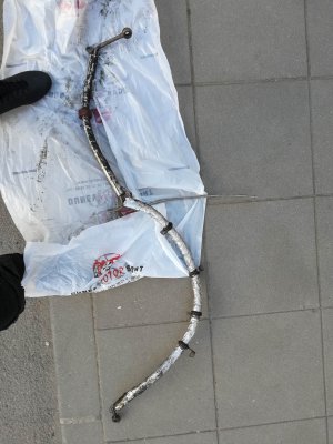
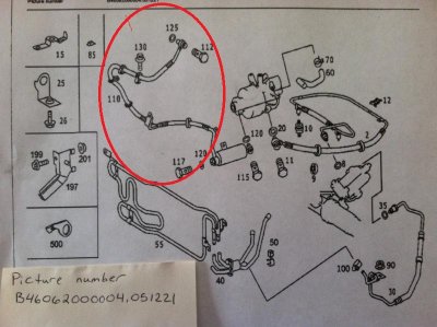
Rear accumulator removed showing feed pipe.

2afzio7.jpg
New rear accumulator fitted. It is this accumulator that takes up the impact (compression) shock of the rear suspensions

110aae9.jpg
Rear valve block with attached rebound accumulator before removal The rebound accumulator takes up the rebound (expansion) shock of both front and rear suspension.
Oil showing on parts prior to removal, is deep penetrating anti-sieze oil to aid dismantling of nuts, bolts, connections and fixings.

2s8fp5h.jpg

Rear valve block removed showing only hydraulic pipes
Remember I said earlier that things do not often work out as planned – well now this story gets juicy. All the connecting hydraulic pipes disconnected without a problem except pipe line to port FB1 feeding the rear left suspension. It just would not budge. I called the attention of the owner and showed him the problem. I showed him all the tools available to disconnect the hose and made him aware that I would have to resort to brutal methods to dismantle the connection. Taking all into consideration, I was given the go ahead to proceed.

15508c5.jpg
The 1st tool used was a standard 17m open end spanner. 2nd tool used was an open end ringed hose spanner and this too did not budge the connection. This was when the problem was identified and brought to the attention of the owner. 3rd tool used was a 17m crow foot spanner with an extension bar to provide leverage. This too did not work. 4th tool was an adjustable locking wrench spanner with squirts of liquid nitrogen to freeze shrink the connection. After repeated attempts, slight turning of the connection was achieved. The 5th and final tool used was a lockable griping plier. The hose connection was turned clockwise and anticlockwise slowly and repeatedly until it was freed. The entire procedure of freeing the connection took about an hour. Care had to be taken not to break the hose pipe and not to put excessive load on the aluminium valve block body which could cause it to crack.

skukae.jpg
Hose connection after it had been freed showing corrosive bond on the first four thread splines. There was no damage what so ever to the aluminium block connection. The threading was then picked out and cleaned and I’m glad to say when it was finally fitted back it threaded properly and did not leak. I did coat the threading on the hose end with white grease to stop further chemical reaction and binding (locking) in the future.

dxnyb.jpg

Dismantled valve block showing height adjustment and shut off solenoids

10714it.jpg

Shut off solenoids showing deterioration of seals and washers

347fuow.jpg

Height adjusting solenoids showing deterioration of seals and washers[/B
]

ehacr9.jpg
Rebuilt solenoids coupled to valve block body and all electrical sockets and points coated with di-electric grease to avoid electrical connection failure

30mmo0y.jpg
Completely rebuilt valve block back in its position under and forward of the left rear wheel. The system was then tested for leaks and function (including the connection to rear accumulator) and the results were excellent.
At this stage I measured the ride heights and requested the owner to take the car for a 15 min drive to warm up the hydraulic fluid and on return to check again for leaks and any visible drop in ride height. Again results were excellent.
Now that the rear had been taken care of, I proceeded to the front of the car to service and repair the front valve block assembly which was leaking internally and causing the front suspension to drop after being parked and over a few hours.

2v2uv04.jpg

Front valve block in the process of being removed
Again, oil stains are from earlier spray of deep penetrating anti-seize oil.
All the hose connections came off without any problems and the front valve block assembly was brought to the work bench for dis-assembly. Brackets, fixings and attached rebound accumulator which takes up the impact (compression) shock for the front suspension all came off easily too.
The height adjusting solenoids twisted off and detached from the aluminium valve body without any issues.
The shut off solenoids were the last to be detached. The left shut off solenoid was very stiff, but it eventually detached as it should. However, the right shut off solenoid refused to budge.
The owner of the car had come down to the workshop and was watching the dis-assembly procedure and witnessed the problem that had now reared its head.
Dry cloths were used to grip and attempt to turn the solenoid to its detaching position but it would not turn. Clamps were used and still it would not turn. The good old vice was applied but still the solenoid would not turn and detach. Witnessing the efforts and failed attempts of the solenoid removal, the owner asked if he should purchase a new valve block, it was that serious.
After an hour of failed attempts, I decided that since I had a spare shut off solenoid at hand, I would saw (cut) off the stuck solenoid so as to remove it from the aluminium valve block. It was apparent to the owner that there was no other remedy so I was given the go ahead to exercise this emergency surgery procedure.
Using a thin blade disc and an air drill, the solenoid was cut off and I was able to remove the entire solenoid without any damage or scaring to the aluminium valve block.

14uvmuw.jpg

Sawn (chopped) shut off solenoid
The air of panic subsided and all the seals were replaced with new ones. The solenoids fitted (with the spare I had) and the re-assembled unit was fitted to the car.
(Phone battery had run dead and this was not the time to recharge so unfortunately pictures stopped)
The ABC hydraulic system reservoir was filled (slightly above max point) to compensate for hydraulic loss and air gaps and the system was started and primed. There were no leaks and the suspension worked perfectly, raising and lowering and maintaining its ride height. Hydraulic fluid levels were topped up to the required quantities and mark and all the under body panels were securely bolted.
The W215 CL500 had undergone major surgery but the outcome was good.

11mevlv.jpg
The next day, I got a text from the owner that ride height had maintained overnight and a day later another text that the height was still holding and everything was working perfect.
Car and owner are presently back in Leeds and all four AMG 19” wheels are being professionally cleaned, skimmed and polished.

Thanks for reading.
 
Would like to thank crownhouse for his workmanship and advice relating to this repair. :thumb:

The day certainly presented its challenges which even i didn't prepare for but we managed to get to the end result. :wallbash:

The drive back home was certainly different. The car felt smoother, the ride lovely and dampend and when i hit the ABC Sport button the chassis instantly felt firmer, something which i never experienced before.

When i was younger I used to sell these cars between £76-£125k +. Back then i knew this car was special and albeit the ownership can be troublesome...... i'd always say it's worth it! :bannana:
 
Very interesting post, thank you for documenting it all!

The only thing I could add would be that the accumulators don't serve as shock absorbers in any meaningful sense. The purpose of the two large ones is to maintain the system pressure when the suspension plungers are quickly extended (and the pump can't keep up).

The smaller one is present on the rear axle to offset the increased flow resistance caused by the longer return pipe to the oil cooler.
 
Accumulators Primary and Secondary functions

“The only thing I could add would be that the accumulators don't serve as shock absorbers in any meaningful sense. The purpose of the two large ones is to maintain the system pressure when the suspension plungers are quickly extended (and the pump can't keep up). The smaller one is present on the rear axle to offset the increased flow resistance caused by the longer return pipe to the oil cooler.”

Dear Forum Member, I partially agree with your comment (above) but here are some points that do not all together agree with your specific phrase “meaningful sense”.

It is common knowledge that when we experience a very hard suspension and additionally the ABC-oil level in the reservoir does not sink to the lower value on engine start, then the two or either of the accumulators (front and rear axle) can be defective. With strong bumps a brief red ABC message comes on the screen, even though the pressure of the tandem pump is still about 190 bar. As it gets worse, this message will come on even with small bumps. The diagnosis then gives the error C1525-016: level calibration has not been performed successfully. New accumulators are the solution to the problem.

Because ride becomes hard and bouncy due to accumulator sphere damage, this shows the (partial) shock absorption property of the compressed nitrogen and diaphragm setup of accumulator spheres.

In my post I talked about shock absorption with regards to compression and rebound and these effects can be smoothened out with springs, air or any decompressable material. There was a time when bicycles only had the air in their tyres as a means of absorbing shocks. Then springs in the riders’ seat were introduced to further enhance a smoother ride. With purpose built cylinder shock absorbers, the spring eventually gave way to advanced systems.
2wqwcnk.jpg
The Mercedes W215 W220 vehicles using ABC Hydraulic systems use several components (all working in tandem) to absorb shock.
These include: 1. The Air in tyres 2. Rubber in bushes 3. Gas filled Shock absorbers 4. Pressure accumulators and 5. Foam in the seats of the car.

The hydraulic accumulators store fluid under pressure and serve a number of functions within a hydraulic system. With a specific amount of fluid stored under pressure it is released when required to perform a specific task in the hydraulic system. The accumulators provide several functions, which are:
• Energy storage
• Compensation of temperature fluctuations
• Cushioning of pressure shocks
• Reduction of Fluid Hammer during sudden switching of valves
• Dampening vibrations
• Leakage compensation of internal seals and valves

Applications that utilise large flows at high speeds primarily use accumulators for energy storage. When required, the accumulator pushes fluid into the hydraulic circuit to add to the pump flow. When the actuators in the hydraulic system are not in motion, the accumulator will refill. Accumulators can also operate as energy sources during normal operation of the system (i.e. cushioning).

Gas-pressurised accumulators use nitrogen both because it is relatively inert. This prevents danger of explosion in case of leakage of the bladder, diaphragm or piston. Also, nitrogen is relatively cheap because it is the most abundant gas in our atmosphere.

Hydraulic fluid is not very compressible and in fact, hydraulic oil will compress less than 0.5% per 1,000 psi. So at an astounding pressure of 10,000 psi, oil will be compressed by a measly 4%. In actual hydraulic systems, the compression can actually be higher due to entrained air within the oil.
Decompression of high pressure fluids are a definite concern, as a lot of energy can be released, that energy release typically happens in fractions of a second. High pressure systems, require sub circuits such as (gas filled) Accumulators to control decompression. Gases are highly compressible.
The short explanation of accumulator operation is this: Air bag is filled with gas, hydraulic fluid is squeezed into the space taken up by the gas, gas tries to push out the hydraulic fluid, and opening a downstream valve allows the gas to push out the hydraulic fluid. This is done to store energy, to compensate for leakage or to reduce shock or vibration.
Because a small pump can be used with an accumulator to provide high flow in hydraulic systems, size and cost are saved on the pump which is the prime oil mover making this combination method of storing energy, economical and efficient.
Energy storage doesn’t have to be for continuous cycling, and the accumulators are used for emergency energy during pump failure. The pressurized fluid in the accumulator (with the shut-off solenoids) can be used to retain pressure in the system to move the vehicle to a safe position where it can stay until power is restored or the malfunction corrected.
For use as leakage compensation, an accumulator can last for extended periods of time. An accumulator can provide constant pressure, even while flow is slowly lost to leakage through piston seals or control valve clearances. When accumulator pressure drops to a critical point, a pressure switch will tell the pump to come on for only as long as it takes to refill the accumulator.

Because of the physical properties of hydraulic fluid, it is easy to transmit shock and vibration through the pipes, tubes and hoses of the system. Some pumps, for example, create pulses of pressure when the pistons or gears reach their outlet port. Accumulators built into the system absorb these pulses and shocks like the struts on your cars suspension, absorbing bumps in the road and providing smoother operation.
Sometimes pressure spikes are quite large, but by adding an accumulator into the return line, decompression shocks can be absorbed and prevent damage to the downstream components, which in a return line, are often not rated for high pressure.

History
The first Hydraulic accumulator was made by William Armstrong in 1846 where he built a crane powered by water of the town mains at Newcastle, United Kingdom.

Accumulators are devices used to store fluid power to do the following:
• Dampen pulsations and shocks of a periodic nature
• Increase the speed of the operational circuit.
• Standby power supply circuits.
• Surge reduction circuits
• Compensate for internal leakage

Accumulators
• A Hydraulic Accumulator is energy storage device.
• It is pressure storage reservoir in which a non-compressible hydraulic fluid is held under pressure by an external source.
• The external source used can be a spring, a raised weight, or a compressed gas.
• The main reasons that an accumulator is used in a hydraulic system, is that the pump doesn’t need to be so large to cope with extremes of demand and supply circuit can respond quickly to any temporary demand and to smooth pulsation.

Benefits of the Accumulator
• Lower installed system costs, accumulator assisted hydraulics can reduce the size of the pump and electric motor which results in a smaller amount of oil used, a smaller reservoir and reduced equipment costs.
• Less leakage and maintenance costs, the ability to reduce system shocks will prolong component life, reduce leakage from pipe joints and minimize hydraulic system maintenance costs.
• Improved performance, low inertia bladder accumulators can provide instantaneous response time to meet peak flow requirements. They can also help to achieve constant pressure in systems using variable displacement pumps for improved productivity and quality.
• Reduced noise levels, reduced pump and motor size couple with system shock absorption overall machine sound levels and results in higher operator productivity.
• Flexible design approaches. A wide range of accumulator types and sizes, including accessory items, provides a versatile and easy to apply design approach.
• Reduced energy costs, cost savings of up to 33% are achievable in high performance industrial machinery using accumulators.
34rdavb.jpg
Diaphragm Accumulators used in the W215 and W220 are similar to bladder type, expect an elastomeric diaphragm is used in place of a bag.
• This would typically reduce the usable volume of the accumulator, so the diaphragm accumulator may not have volume capacity of a bladder accumulator.
• Diaphragm accumulator may be spherical or cylindrical.
• The main difference with bladder accumulator is an increased maximum compression ratio of approximately 8:1
• It is low weight, compact design and good for shock applications (good response characteristics)
Their main Advantage: Highest efficiency with tests showing 97 percent energy retainment.
Their main Disadvantage: Nitrogen will permeate the foam bladder material over time and need to be periodically recharged.

W215 / W220 ABC Hydraulic System
The hydraulic system in the Mercedes type 215 and 220 contains about 4 litres of CHF11s fully synthetic oil.
The pressure supply operates in normal driving operation with an ABC-oil pressure between 180 and 200 bar.
Pressure peaks in the system are intercepted in the front valve unit pressure supply (52) by a pulsation damper (52a). This unit prevents and relieves pressures over 200 bar through a pressure relief valve. Also in the return manifold at the front valve block unit Y36 / 1 and in the pressure valve unit 52 along with its pulsation damper (52a) are back pressure valves running a minimum pressure of 10 bar in the return line as a system safely.
In the main steel-pressure accumulators, a membrane separates the oil chamber from the gas chamber with a gas volume of 650 cc, gas pressure is 100 bar, but imprinted outside the Pulsation sphere is value of 200 bar.

2ntb4n6.jpg
Working pressure: red, control pressure: blue, return: green
1 tandem pump, 2a oil filter, 9 oil radiator, 9 oil cooler, 53 accumulator return, B4 / 5 pressure sensor, y1 control valve, y2 check valve , 14 accumulators front, 4 axles accumulators rear axles, B40 / 1 temperature sensor, 52 pulsation dampener, 52b pressure relief valve 56/57 vent valves

Citroen Pressurized Spheres
A fundamental component of the Citroën hydraulic system is the pressurized sphere. They are used for a variety of purposes, Pressure maintenance, Height levelling, Load bearing and Shock absorption; but each one functions in exactly the same way.

The Main Accumulator
The first use of a pressurized sphere is as the main accumulator. It collects high-pressure fluid from the pump and distributes it to the subsystems. It is connected to an electronic pressure regulator switch. When pressure is low, e.g. at start-up time, the switch is tripped, engaging the pump, filling the pressurized sphere with fluid. When the pressure inside the sphere reaches a certain point the switch is cut and the supply of high-pressure fluid stops.
34nicrq.jpg
Each of the subsystems draws more or less directly from this sphere as pressure is needed to perform its specific function. Even if there is a constant draw on the accumulated high-pressure fluid, the pump will only be engaged intermittently to ensure that the pressure in the accumulator never gets too low.

The "Load-bearing" Shocks
Each load-bearing shock is a simple piston with a pressurized sphere on top of it. Hydraulic fluid can pass back and forth between the piston and the sphere. The pressure of the compressed nitrogen in the sphere counteracts the force of the weight of the body. In this way the spheres function as springs or torsion bars would in conventional cars. An iris in the orifice between the piston and the sphere produces a dampening effect.
opa8ap.jpg
Pressure flows from the hydraulic circuit to the suspension cylinders, pressurizing the bottom part of the spheres and suspension cylinders. Suspension works by means of a piston forcing hydraulic fluid into the sphere, compacting the nitrogen in the upper part of the sphere; damping is provided by a two-way 'leaf valve' in the opening of the sphere. Hydraulic fluid has to squeeze back and forth through this valve which causes resistance and controls the suspension movements. It is the simplest damper and one of the most efficient.

The Mercedes W215 / W220 hydraulic suspension
3004rrt.jpg
41 Rear suspension strut
a - Rubber mount jounce stop n - Suspension strut support bearing
b - Top wiper o - Hydraulic pipe
c - Top spring plate p - Top guide sleeve
d - Piston rod tube q - High-pressure seal
e - Piston rod r - Steel spring
f - Position magnet s - Protective boot
g - Hydraulic cylinder t - Hydraulic cylinder bottom stop
h - Bottom guide sleeve u - Shock absorber piston rod
i - Bottom wiper v - Shock absorber
j - Inner bump stop w - Lower mount
k - Outer bump stop x - High-pressure seal
l - Bottom spring plate
m - Rubber mount rebound stop
B22/1 - Left rear suspension strut motion sensor
822/ - Right rear suspension strut motion sensor

The suspension strut forms a unit comprising hydraulic cylinder, steel spring and shock absorber. The suspension strut motion sensor is integrated in the hydraulic cylinder. The shock absorber is a twin-tube shock absorber with gas preload.

Function
The weight of the vehicle is supported by the oil in the hydraulic cylinder and by a coil spring connected in series. The coil spring is supported at the wheel on a spring plate rigidly connected to the shock absorber tube. The spring is supported at the body on the single-acting hydraulic cylinder (plunger).

By adjusting the hydraulic cylinder in the direction of the suspension strut and the resultant change in spring length, additional forces are produced which influence the suspension and damping in the frequency range up to 5 Hertz.
The vehicle level is raised and lowered by filling and emptying the oil chamber which reduces or increases the length of the suspension strut as a result.
To move the hydraulic cylinder out or in, oil is delivered to the suspension strut or oil flows out of the suspension strut into the return flow circuit.
A passive twin-tube gas pressure shock absorber connected in parallel with the hydraulic cylinder and suspension strut is responsible for damping the higher frequency wheel vibrations. The hydraulic cylinder takes over the active damping of the lower frequency body vibrations.
2j4evtj.jpg
A Pressurised Condition B Depressurised Condition
g- Hydraulic cylinder y- oil chamber r- steel spring v- shock absorber
35d8ci8.jpg

rj15py.jpg
In my conclusion, the accumulators’ Primary purpose is to store energy and maintain pulse free pressure in the system during operation. However (as in the Citroen system) the accumulators also have a Secondary purpose of assisting the system (of included gas shock absorbers) in the dampening of compression, rebound and liner shocks occurring in both static and dynamic use.
 
Great info/write up, thanks. Only problem now my head hurts :doh:

Matt
 
In my conclusion, the accumulators’ Primary purpose is to store energy and maintain pulse free pressure in the system during operation. However (as in the Citroen system) the accumulators also have a Secondary purpose of assisting the system (of included gas shock absorbers) in the dampening of compression, rebound and liner shocks occurring in both static and dynamic use.
I think I can agree with that. The only reason I'm cautious about discussing the accumulators' impact on suspension damping is that there's a alot of misunderstanding about their purpose and I wince every time I see someone on a forum say that you can test the state of the accumulators by bouncing the front or rear of the car...

Incidentally, I replaced my return accumulator and pulsation damper yesterday along with a fluid flush. I wasn't having any issues but at 120k miles I thought it was probably a decent idea (the front and rear accumulators were changed last year). I haven't noticed any change in handling or ride, however.

I certainly support your statement / observation above and I am also glad that you have brought this to the attention of other readers.
As I have mentioned the accumulators Secondary Function is to aid suspension (it is not it's Primary function). The accumulators Main (Primary) Function is to dampen the effects of hydraulic pressure in the system. As such and also because of the pressure at which the accumulators supports the suspension in its Secondary (lesser) Function, it is NOT POSSIBLE to determine / test their functionality by bouncing the front or rear of the car when the car is stationary. Effects of an accumulator can only be felt while driving over bumps.
The best and surest way to know if your accumulators are faulty is to observe the difference in levels of the oil reservoir when the engine is running and when the engine is off . . . as follows:
" The dipstick has 2 readings Engine On ("Auf") - which is the lower indentation and Engine Off ("Aus") - the higher indentation. On level ground with the system warmed and the engine running, the level on the dip stick should be closer to the lower Engine On ("Auf") mark. On level ground with the engine off and the system left to settle for about 15-20 minutes, the level on the dip-stick should rise closer to the Engine Off ("Aus") mark. If this change in level of the oil in the reservoir is not apparent, or if the change in levels are negligible, it indicates blown accumulator/s".
 
I have very recently changed all the accumulators on my ABC hydraulic system and to give readers an indication of the difference in oil levels with the engine on and off, I have included pictures as a means (benchmark) for comparison.

The best and surest way to know if your accumulators are faulty is to observe the difference in levels of the oil reservoir when the engine is running and when the engine is off
6zwy6x.jpg


" The dipstick has 2 readings Engine On ("Auf") - which is the lower indentation and Engine Off ("Aus") - the higher indentation.
2jequpv.jpg


On level ground with the Hydraulic System warmed and the engine running at idle, the level on the dip stick should be closer to the lower Engine On ("Auf") mark.
2wp34sw.jpg


On level ground with the engine off and the system left to settle for about 15-20 minutes, the level on the dip-stick should rise closer to the Engine Off ("Aus") mark.
28i12ew.jpg


If this change in level of the oil in the reservoir is not apparent, or if the change in levels are negligible, it indicates blown accumulator/s".

I hope the pictures help.
 
Hi crownhouse,

I have sent you an email a few weeks ago. Have you received it ?
Thanks
Isa
 
Hi,
I wonder if you could help me.
I have recently bought a 2004 cl500 and the other morning when I went to the car, I noticed that the front nearside wheel was right up in the wheel arch. I've checked the ABC fluid, it will need a little amount but not much at all.

I started up the car, raised and lowered it and it seems to be at the right height, but will check again tomorrow.

Do you know what part might be causing the problem?
 
Could you fix my CL500 too?

Hi Crownhouse,

Awesome thread, I'm sure this has kept many CL500's alive and on the road! You hero.

I was tempted to give his a go but time is short and I want to use the car, I have used it as daily since a couple of months back, I believe the previous owner saw this coming and sold it sharpish. It is otherwise completely mint and awesome colour combination.

Would you be able to carry out the same work to my car? I believe from my reason. Of your thread that at least one accumulator has given up, another may be on the way out, I think a strut may have a slight leak and the pump seems to be fine. The car only leans on one side, with the offside rear being mainly dropped. The first time the warning came up was after a 6 hour drive and I heard a funny noise come from the passenger footwell area. It corrected itself and wasn't a problem for a while but is now red warning and always leaning on one side.

Let me know if I can bring it to you and where/how I can get hold of you?

Nice one. Toby
 
Operation of Bleed Screws

Hi all,

I'm looking at doing this work but cannot find any info on the operation of the beed screws (item 56 front & 57 rear in schematic above). I need to remove and repair the front valve block therefore please can someone confirm the following:

* Will one bleed screw (the easiest being the nearside left) be sufficient to release hydraulic pressure in the system so that it is safe to remove the front valve block?
* How do you operate the bleed screw to safely reduce system pressure?

Thanks in advance
Andy
 
The bleed screws tend to corrode and snap off if you try to open them. Once the engine is switched off and the wheels on both axle are off the ground the hydraulic pressure in the system drops fairly rapidly - I've never had any issue just slowly unbolting the hydraulic lines from the valve block. Just make sure that both sides of the front axle are supported on stands.
 
The bleed screws tend to corrode and snap off if you try to open them. Once the engine is switched off and the wheels on both axle are off the ground the hydraulic pressure in the system drops fairly rapidly - I've never had any issue just slowly unbolting the hydraulic lines from the valve block. Just make sure that both sides of the front axle are supported on stands.

What if I'm only able to lift the front axle off the ground when working?

Won't the rear non-return valves prevent the rear axle lowering?
 
Sorry, should have said "Once the engine is switched off and the wheels on both side of the axle are off the ground the hydraulic pressure in the system drops fairly rapidly".

You only need to take the weight off the front two wheels when working on the front valve block.
 
Sorry, should have said "Once the engine is switched off and the wheels on both side of the axle are off the ground the hydraulic pressure in the system drops fairly rapidly".

You only need to take the weight off the front two wheels when working on the front valve block.

Cheers, thanks a lot for clarifying.
 
Non-Return Valves

Has anyone experienced problems removing the non-return valves (the two smaller valves out of the four). Both of the non-return valves can be rotated to 'unlock' them from the manifold but they cannot be removed. It feels to me as if a vacuum is present preventing the valves from being removed (i.e. pulled out).

The larger valves were similar however due to their size they are easier to grip with hands and I have been able to remove these. The smaller valves are almost impossible to grip.

If anyone has experienced similar issues or has any suggestions how I might be able to grip the smaller valves to pull them from the manifold I'd really appreciate some guidance.

I used a big pair of grips and gently wiggled them out
 
Thanks for the thorough thread.

I just registered because of it, seems you know ABC in here.

I am a fresh CL500 (c215) owner, a pretty mint one on 150k kilometers, with 3-5 years of sitting in a garage, probably because of the ABC.

Car hasn't got a single fault, only one ABC hose gets me mad. It broke 3 times already for 7k km. First two times I repaired it with the hydraulic specialists, didn't work, I got a second hand one now installed. Scheduled for next month is complete revision (replacing) of the accumulators, etc. Could the reason for the breaks be these accumulators?

Also, another question - the last re-install of the hose I noticed it isn't holding as well as it is meant to be. Could this be an issue? Also, the metal cover is a bit ripped as you can see in the linked image - flammable? (abc hose) Is the placement over the gears correct at all? It's completely loose - none of the holding points are connected.
 

Attachments

  • 30652656_1701992579869780_2568080045721518080_n.jpg
    30652656_1701992579869780_2568080045721518080_n.jpg
    387.9 KB · Views: 11
  • photo 4.jpg
    photo 4.jpg
    116.6 KB · Views: 12
Hydraulic dampner needs replacing . If it falls, you'll get bursts of pressure that can cause that hose to fail. Replace all accumulators
 

Users who are viewing this thread

Back
Top Bottom