• The Forums are now open to new registrations, adverts are also being de-tuned.

Anti roll bar snapped

Steel hollow bar is a common product in all diameters.
Depending on the diameter and the intended use, it can be seamless or seam-welded.
Round-section hollow bar can be hot-rolled - OR - cold-drawn and annealed.

Couple of questions for the man that knows springs.
Is there a rule of thumb diameter at which the shift from solid to hollow occurs (two bars I have here - 11 and 13mm OD - are solid) How much larger OD before the decision to go hollow and is there an accepted/standard/common wall thickness?

If I wanted a very simple ARB (ie straight with two kinked arms, no other bends and no requirement for mounting eyes) are there companies in the UK who would undertake this at reasonable cost? In my mind it is cut a suitable bar to length, bend in two places, heat treat - expensive?
TIA.
 
That's a good question, Bellow.
1. It's pretty obvious that the more metal you take out of the middle, the less final strength you have.
2. The strength is largely determined by the cross-sectional area (XSA) of the metal. (Other metallurgical factors, such as the grade and temper of the steel, also play a major role).
3. For a given outside diameter (OD), the relationship between the wall thickness (WT) and the XSA is not linear, but is a square-law relationship.
(Work it out for yourself).

I was surprised to read in this thread that anti-roll bars are not all solid. I didn't know that.
I don't know of a rule of thumb diameter at which the shift from solid to hollow occurs, but, from point #3 above, it isn't a simple decision, as a number of factors come into play.
Manufacturers are at pains to reduce weight.
By the use of stronger grades of steel, this can be done by reducing the OD of a bar without sacrificing the functional strength, but you then have the problem of clamping it and making attachments to it.
This is clearly easier when you aim for a larger diameter and take the metal out of the bore to reduce weight - thus maintaining the XSA and the strength.

We might be surprised to find that anti-roll bars are hollow, but we expect other structural steel components in construction to be hollow sections.
Circular hollow section and rectangular hollow section beams are common welded components in bridges, buildings, vehicles and similar engineering structures.

Re. your second question ...... Tube and bar bending is commonly undertaken in engineering and fabrication work-shops.
They will often sub-contract the stress-relieving and final heat treatment to specialists in this field - although some fabrication shops will do their own.
You may find the heat treatment more expensive than the forming.

This is me thinking aloud.
Vehicle engineering is not my field of expertise, but my working life has been spent in the manufacture and testing of tubes and bars ... mostly for safety-critical applications in the marine world or in offshore oil and gas.
 
@Worcestershire did you manage to get sorted? Just to you know you are not alone, both of my rear coil springs on my W218 CLS were found to have been snapped at the very top coil. Car is a 2012 with 54k miles. Wont be replacing them with MB items, but uprated them to H&R offerings.
 
There’s an argument that material in the centre of the anti roll bar does little to resist torsional forces. Hollow bars can be just a few millimetres larger diameter for the same performance at about half the weight.
 
I'm pretty sure you're right Atavus.
However, the cyclic stresses on the ARB are not only torsional, but a complex mix of stresses.
 
Ah! The humble front anti-roll bar, or FARB in motorsport speak.
I do know there is often a huge discrepancy between the calculated stiffness of the bars, and the actual installed stiffness.
I wonder if the same applies to the stress calcs ?
FARBs come in all shapes and sizes from the conventional road car types, to motorsport types with a tube torsion section with detachable lever arms, to what look like miniature drive shafts, to just a stack of Belville washers.
Good input here from Johnsco and Atavus and it is conventional to use tube rather than bar once the diameter gets to about an inch.

I first got really interested in such things in the 80's when running the huge 'aeroplane' V12 engines in the Slik Cut Jaguars. A 250kg engine in a 850kg car and the engine tends to rather dominate things dynamically especially when the engine C of G is so high. the drivers described the engine as 'wanting to get over their shoulder' at low speed when there has not the blanket of downforce to paint the car onto the road as there was at high speed.
We found using a stiffer FARB made things better, but when I used a solid damper, a bottle jack, a load cell and DTI to measure the installed stiffness of the bar, it was nothing like the designer calculations. A combination of lost motion in joints, flex in lever arms and displacement of links meant that he actual working part of the bar was not being 'driven' correctly.
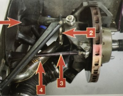
So we invented a huge one piece carbon bar of almost 3" diameter with integral arms and very short links directly too the uprights.
IMG_0034.jpeg IMG_0035.jpeg
The number on the bar (arrow 4) is the deflection in mm with 500kgs hanging off one end on the test rig. Difficult to do calcs for hand laid up carbon components, so each one was test calibrated.....and they were stiff!
The front roll stiffness helped with aero platform and also helped keep the engine from feeling like it was going to overtake the driver.
With this somewhat unconventional solution the car achieved 2x World Championships and 2x Le Man wins.

Fast forward to the 90's and I was running the Gulf Mclaren's designed by Gordon Murray. He maintained that if the structure of the car was right, then the car only needed one roll bar, and he put it at the front. With another big V12 engine ( this time a BMW of 240kgs in a 1100kg car) the drivers were describing the same sensations as the V12 Jaguar. So I decided to check the actual installed roll stiffness of the one ARB. ....and it was virtually zero!
The design cals for the bar and arms were all good, but this time the mounts in the side of the composite front structure were just walking about!
I had the dubious honour of telling Gordon that his car effectively had no roll bars!

Things have improved in more recent times with FE, CAD and most of all the dynamic rig tests, but as recently as 9 years ago I stumbled across another example at Lotus. Yes, these are the guys who really know about suspension!

I was asked to develop a GT4 race version on the Evora. The ARB's on the road car were very standard type road car ARB's with all the constraints of getting a bar from one side of the car to the other whilst avoiding the other road car components. The Engineering dept offered a number of different rates for the GT4 race car, but I thought I would check one myself against the quoted rating.
Lo and behold! Only about 30% of their calculated stiffness when installed in the car!
They verified my method and went back to the CAD screen to add few real world and 'in context' adjustments to the calculations!
 
Ah! The humble front anti-roll bar, or FARB in motorsport speak.
Very interesting post.
I do know there is often a huge discrepancy between the calculated stiffness of the bars, and the actual installed stiffness.
I wonder if the same applies to the stress calcs ?
Presumably, if the calculated stiffness is significantly greater than the installed stiffness then maybe the torsional deflection for any given load is higher than calculated, hence promoting fatigue failure? Having said that, there are a variety of reasons why the stiffness as calculated could be compromised including, as you mention, flexibility in mounts and imperfect joint stiffness, that would invalidate that proposition.
They verified my method and went back to the CAD screen to add few real world and 'in context' adjustments to the calculations!
The age-old problem of physics vs. engineering ;)

When the model doesn't accurately reflect reality, it's invariably because the model is incomplete - either through incorrect application of principles, or (more likely) because the model makes assumptions about how other elements of the system perform that aren't truly valid.

Engineering's great fun, isn't it? :)
 
Yes, it is great fun! And always an adventure.
Was it Keith Duckworth of Cosworth said that Engineers are only here to make up for the inadequacies in Designers?

I'm lucky to have worked with some really good ones.
 
Interesting post Mactech, cheers.

Fast forward to the 90's and I was running the Gulf Mclaren's designed by Gordon Murray. He maintained that if the structure of the car was right, then the car only needed one roll bar, and he put it at the front.

For a car as singleminded as a race car, that would be true.

With another big V12 engine ( this time a BMW of 240kgs in a 1100kg car) the drivers were describing the same sensations as the V12 Jaguar. So I decided to check the actual installed roll stiffness of the one ARB. ....and it was virtually zero!
The design cals for the bar and arms were all good, but this time the mounts in the side of the composite front structure were just walking about!
I had the dubious honour of telling Gordon that his car effectively had no roll bars!
!

So a certain amount of bending (of the arms) is factored in as the bar's ultimate stiffness. The portion between the arm and the bar's first chassis mount though would see both bending and torsion. The bending there - wouldn't transfer to the other end of the bar as it is in a plane that denies a torsional input to the bar? If so, that part of the bar is no more that a single bump single wheel spring? Noticeably, the CF bar on the Jaguar dispenses with any overhang there!
 
Interesting post Mactech, cheers.


For a car as singleminded as a race car, that would be true.


So a certain amount of bending (of the arms) is factored in as the bar's ultimate stiffness. The portion between the arm and the bar's first chassis mount though would see both bending and torsion. The bending there - wouldn't transfer to the other end of the bar as it is in a plane that denies a torsional input to the bar? If so, that part of the bar is no more that a single bump single wheel spring? Noticeably, the CF bar on the Jaguar dispenses with any overhang there!

The simplest model of an anti-roll bar is two arms driving a length of bar. Beam loading means the arms bend, and then added to the torsional defection in the bar.
Of course, it never really works like that as there are joints which cannot be assumed to be ultimately stiff and drop links which behave in totally different ways wether in tension on compression. The arms are never quite at 90 deg to the bar so there are complex bending loads.
Another example is when adjustable twisting blade ARB's were in vogue. (The blade replacing one or both arms) They worked well in soft (blade bending) mode, but as the blades twisted to the stiffer vertical position, they tended to get pushed sideways by long drop links. This created variable load dependant on displacement!

As Phil says, if the model does not represent the real installed condition, then the results of calculations can be less than useful.
Goodness only knows how you calculate the stresses in the typical contorted current road car ARB's!
 
That might explain why I've not seen a blade type ARB in a while.

Is there a rule of thumb for FARB stiffness relative to the spring? Theoretically, for the roll situation, the bar could be infinitely stiff and merely be a linkage between the two road springs. But they are invariably less than than that so have a spring rate relative to the wheel rate. Is there a preferred ratio for getting the required roll stiffness? Is the FARB's stiffness decided as secondary (to gain required roll stiffness) after the wheel rate is selected to deal with aero loads? On a non downforce car, is the relative stiffnesses between wheel and bar more open - with a preferable ratio? At the wheel, which has the higher rate - the spring or the bar?
Correct to believe that roll centre heights for a tarmac circuit racer are determined - or rather, dictated - by geometry that controls camber change with a view to maximising the tyre contact patches' contact with the tarmac?

I looked further (after Johnsco's posts) into heat treatment for spring steel. Constantly the refrain is hardening and tempering. Hardening to gain the spring stiffness and tempering to remove the residual stresses? Are they the processes required to make a bar of appropriate carbon content into an ARB/spring after the bar has been bent (at red heat) to the required shape?
 
Unfortunately everything is so interactive. As you have pointed out there are just so many variables starting with the c of g, roll centre heights and the wheel rates required to support the assumed loads.
Back in the pre-downforce days roll stiffness of 1/3 wheel rate was common, but as wheel travel has gone for 6" to 6mm things have changed somewhat!
As with damping, geometry and roll stiffness have all become 'bit part' players to support the wheel loads developed by downforce, or even to promote the production of constant useable downforce by maintaining the aero 'platform'
I haven't manufactured conventional ARB's for ages now so can't actually remember the heat treatments.
 
Thanks Mactech - very helpful.
A couple more questions and I'll leave you in peace.

Unfortunately everything is so interactive. As you have pointed out there are just so many variables starting with the c of g, roll centre heights and the wheel rates required to support the assumed loads.
Back in the pre-downforce days roll stiffness of 1/3 wheel rate was common, but as wheel travel has gone for 6" to 6mm things have changed somewhat!

Would that be broadly applicable to the FARB on most road cars do you suppose? (If so, I could better guess the stiffness of any car's FARB by extrapolating form its (easier ascertained ) wheel rate).

As with damping, geometry and roll stiffness have all become 'bit part' players to support the wheel loads developed by downforce, or even to promote the production of constant useable downforce by maintaining the aero 'platform'

I read that as damping being less critical on high downforce cars than might be supposed. Away from high downforce cars, is it the case that the softer the springing, the more critical becomes damping? And, with higher roll centres with less reliance on springs (wheel and ARBs) the damping would be less critical than with low RCs and the reliance on springing to contain roll?

I haven't manufactured conventional ARB's for ages now so can't actually remember the heat treatments.

A local(ish) company with Heat Treatment in its name should know. Wonder if anyone is still there from when I worked there.....
 
Would that be broadly applicable to the FARB on most road cars do you suppose? (If so, I could better guess the stiffness of any car's FARB by extrapolating form its (easier ascertained ) wheel rate).
It's a very rough rule of thumb, but dependant on so many other factors.
I read that as damping being less critical on high downforce cars than might be supposed. Away from high downforce cars, is it the case that the softer the springing, the more critical becomes damping? And, with higher roll centres with less reliance on springs (wheel and ARBs) the damping would be less critical than with low RCs and the reliance on springing to contain roll?
it may be the case that high velocity damping is less critical as the wheel moves less reactive to the car, but the low velocity damping (the bit that controls the car's attitude to the road) is far more critical and is often used as a tuning aid to get the car to sit at a better rake or roll in transient conditions.
 
It's a very rough rule of thumb, but dependant on so many other factors.

Cheers - 'very rough' is closer than I've been and good enough for now!

it may be the case that high velocity damping is less critical as the wheel moves less reactive to the car, but the low velocity damping (the bit that controls the car's attitude to the road) is far more critical and is often used as a tuning aid to get the car to sit at a better rake or roll in transient conditions.

That's an aspect I'm trying to get to grips with. At least partly influencing it is the polar moment of inertia in the longitudinal plane (as viewed in end elevation from front or rear) relative to the roll centre at the end of the car (usually front) that is receiving the roll from the other end before it resists it with its ARB. I did say no more questions though!
Thanks Mactech - much appreciated.
 

Users who are viewing this thread

Back
Top Bottom