• The Forums are now open to new registrations, adverts are also being de-tuned.

How much volt should it be to camshaft sensor?

zibpka

Member
Joined
May 3, 2015
Messages
44
Car
Mercedes benz c220 and c36 amg
Im having trouble with my c36 amg 1996 with the m104 Engine.
Im getting fault code reading: Camshaft sensor: not recognize or implausible

I have concluded that it beginned with the wiring was shorted out so the signal cable was touching the negative feed but i have switched that but it still the same problem.
Is there anyone that know what the input voltage should be from the ecu to the camshaft sensor so i know if the ecu still working?

I have also tried with a different camshaft sensor though i put it in before i got to change the wiring. can i have destroyed the both camshaft sensors?

can i test the camshaft sensor somehow and if that possible how do i do it?
 
12V.

Being a Hall sensor, you can of course test it by giving it +12V, ground and hooking the sensor wire to an oscilloscope.

Touch the sensor with a screwdriver blade and the output waveform on the screen should look similar to this:

hall+wave+form.png
 
12V.

Being a Hall sensor, you can of course test it by giving it +12V, ground and hooking the sensor wire to an oscilloscope.

Touch the sensor with a screwdriver blade and the output waveform on the screen should look similar to this:

hall+wave+form.png


Can it be a Hall sensor when it is only 2 Cables? it is the a round Connector. I Think its a vr. Anyway i don't have an oscillioscope.
I have also measured the signal and its 3,43v and when i checked my c220 with the exact same camshaft sensor it was only 0,28v, Could it be that big of a diffrence?

//
 
You’ve asked about the input voltage from the ECU. If it were a two wire sensor and one was an input voltage from the ECU, this wouldn’t be a sensor as it wouldn’t output the camshaft position back.

If your camshaft sensor has only two wires it is a reluctor. There’s no input from the ECU, only output from the magnetic sensor. It is important to get the polarity right as the sensor would work either way but at higher rpm won’t read right.

You will need an oscilloscope to properly test either of the sensors’ functionality.

Well it would be cheaper for me to just buy a new camshaft sensor than by a oscilloscope

I got the polarity right. The pin in middle is the signal and the outer is the negative and i have also checked the wiring diagram for the main connector and the 8 is the signal and the 19 is the negative so i don't think that is the problem. And they are no longer shortened out.

Well then it's something wrong i assume because when i'm turning on the ignition on the key(not starting the car) it jump ups from 0v to 3,4v directly.

Is it possible to destroy the ecu when the wiring was short circuit?
 
The worst that would happen if you short the two wires on the reluctor sensor is the ECU won’t know where in the engine cycle it is and the car won’t start. I highly doubt you can destroy the ECU by doing that.

If you don’t have the test equipment, get a spare sensor and see if it cures the problem. I’d trace the wires too in case they got damaged.

I have measure the wiring and they are not shorted out at the moment and they connected to the right wiring on the main connecter(gonna replace the wiring sometimes soon) but back to the problem at hand, Why is there voltage from the ECU on that wiring. I also measured it right by the main connector. And this is right by then you turn on the igition. I have tried with a used sensor from another car that worked so i dont know if its necessary to switch to a third one

//
 
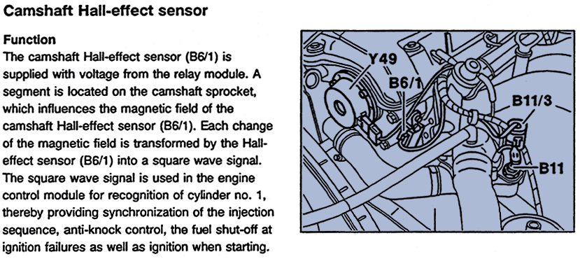
From here:

014bottom.GIF


You're saying that there's only two wires but Hall sensors require 3 with one being +12V. Above snippet confirms that the M104 cam sensor is a Hall type too and the power comes from a relay module.

Have you traced your wires? Are you sure you're looking at the right sensor, i.e. camshaft and not crankshaft?
 
Yes
From here:

014bottom.GIF


You're saying that there's only two wires but Hall sensors require 3 with one being +12V. Above snippet confirms that the M104 cam sensor is a Hall type too and the power comes from a relay module.

Have you traced your wires? Are you sure you're looking at the right sensor, i.e. camshaft and not crankshaft?

Yes it is a coaxial cable and they only contains 2 wires as far as i know. I also know that when i contacted the dealership they also said it was a 3 wire but i know for a fact that the car came with this so i know its the original. The crankshaft sensor it it in the back of the engine closer to the transmission and the sensor im talking about is at the front of the engine. What make me confused is that you said the voltage should come from the sensor and not from the ECU and when i remove the wire from the connector and measure the signal wiring when the ignition turned on there is 3.4v where i assume there should be none?
//
 
Did I really say "the voltage should come from the sensor"? I cannot see where. Maybe you confused the "signal output" with "voltage output".

Take a picture of what you've got and where it plugs in. Otherwise we can go around in circles forever.
 
Yeah sorry i meant the signal. But as i said. What can be the problem if the voltage from the wiring is 3,4v. That doesnt seem to be right?
Yeah gonna take some picture later today.
 
How do i measure my sensor with the oscilloscope? And How should the curve look like?
 
At this stage I'm not even sure we are talking about the same thing. The coax cable may refer to the crankshaft wiring that plugs into the EZL. Nothing to do with the cam position sensor.

I'd forget about the 3.4V or anything else for a moment and get some pictures up.
 
I know the diffrence between the crankshaft sensor and the camshaft sensor so in certain its the camshaft sensor. But im gonna take som picture later today.
 
I dont seem to be able to upload picture. It only saying an error occured. Dont know Why.
 
Anyway i have sent the ECU to a company that gonna look it up. Is there something else that can affect the ECU or the camshaft position sensor to act like this? Like the throttle acuator or the Mass airflow meter?
 
Why isn’t it possible to see How much voltage is on the wires on the eletric schematic?
 
Mercedes don't supply that info ---but to test the OVP you can just measure the voltage between the [ground] connection of your battery and to the terminals 87/87E/87L of the OVP relay, with the ignition on.
Then you should see the same voltage as you can measure across the battery.= 12---13.2 VOLTS
It may be a litle less, but there should not be more than 0.2 Volt of a drop .

ovp circuits
http://www.w124-zone.com/downloads/MB CD/W124/w124CD2/Program/Chassis/54-0242.pdf

some pics of what goes wrong in this thread
What actually fails in an OVP Relay - Mercedes-Benz Forum.

check the OVP inputs and outputs?
 

Users who are viewing this thread

Back
Top Bottom