Navigation
Install the app
How to install the app on iOS
Follow along with the video below to see how to install our site as a web app on your home screen.
Note: This feature may not be available in some browsers.
More options
You are using an out of date browser. It may not display this or other websites correctly.
You should upgrade or use an alternative browser.
You should upgrade or use an alternative browser.
Diesel Benz
MB Enthusiast
The wiring diagram does not show any connectors for the wires between the rear SAM and the rear lamp. What colour are the wires? Any part numbers visible?
OP
OP
Chas
Active Member
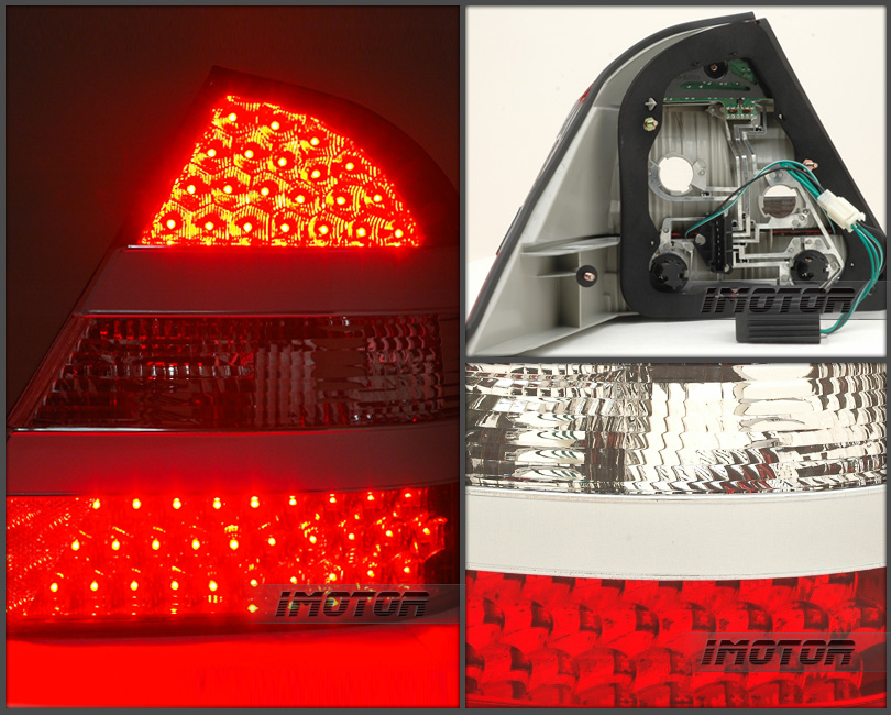
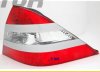
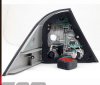
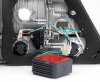
They are after market ( ebay USA ) W221 look alikes. They look great and all is working ok apart from the error in cluster TAIL LIGHT "L". Its possible a wire has come loose from the resistor where they go inside the lamps. The right one is not showing any errors. I swapped resistors but made no difference
Diesel Benz
MB Enthusiast
They are after market ( ebay USA ) W221 look alikes. They look great and all is working ok apart from the error in cluster TAIL LIGHT "L". Its possible a wire has come loose from the resistor where they go inside the lamps. The right one is not showing any errors. I swapped resistors but made no difference
I see, did you measure the current each side draws? Are you sure there are no failed LEDs?
OP
OP
Chas
Active Member
All LEDs are working ok. The two bulbs which are replaced by LED were 4W each. Would increasing the resistor size cure the problem?
My meter is broken so I cant check the current just now.
Just checked, the left hand resistor is not heating up so I guess its not wired properly to the light ( the right one is lukewarm as it should be and not too hot)
My meter is broken so I cant check the current just now.
Just checked, the left hand resistor is not heating up so I guess its not wired properly to the light ( the right one is lukewarm as it should be and not too hot)
Last edited:
OP
OP
Chas
Active Member
I see, did you measure the current each side draws? Are you sure there are no failed LEDs?
Just noticed, there are three tiny Led's on the side of the lamp about 1.5 mm diameter which are not working. Could this cause the resistor to stop working?
Attachments
Last edited:
OP
OP
Chas
Active Member
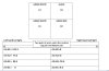
Multimeter readings on both lights
Readings of both tail lights(left one shows up cluster error) below, any experts got any suggestions please ? They both work ok, just the left hand tail light resistor isnt working and shows up in cluster as failed bulb ,thanks
Readings of both tail lights(left one shows up cluster error) below, any experts got any suggestions please ? They both work ok, just the left hand tail light resistor isnt working and shows up in cluster as failed bulb ,thanks
Attachments
Last edited:
Diesel Benz
MB Enthusiast
I'd like to see the wiring diagram of the resistors. Does it have a resistor to ground for each bulb in order to increase the current to the same level as a normal bulb would draw?
Can you measure the resistance from the light connector, from each bulb's feed to ground. Or even better if you have a 12 V source and measure the current each light draws.
Can you measure the resistance from the light connector, from each bulb's feed to ground. Or even better if you have a 12 V source and measure the current each light draws.
Diesel Benz
MB Enthusiast
If the light unit has the same connector pin numbers printed as the original, it should be the following (I'll put wire colours too, you can look from the car harness the pin numbers based on the wire colour if the connector does not have pin numbers). This is for the left tail light:
7: ground, brown
3: stop lamp, black/red (this should be a LED on the original too)
2: turn signal, black/white
5: tail lamp, grey/yellow
1: tail and parking lamp, green/pink
4: reversing lamp, grey/black
5: rear fog, grey/green (left hand steering only)
7: ground, brown
3: stop lamp, black/red (this should be a LED on the original too)
2: turn signal, black/white
5: tail lamp, grey/yellow
1: tail and parking lamp, green/pink
4: reversing lamp, grey/black
5: rear fog, grey/green (left hand steering only)
Diesel Benz
MB Enthusiast
Resistance from the light connector, from each bulb's feed to ground
Does "0" mean a short circuit or an open circut (0 ohms should be a short circuit but you should not see a working light in that case).
Can you remove the bulbs? Is the resistor still connected? Can you measure the resistance without bulbs?
What sort of multimeter do you have and which ohm range are you using it? The resistance of LEDs isn't really straightforward, this is why it would be better to measure the current drawn at normal operating voltage, or just the resistance of the additional resistors. Also keep the plus wire of the multimeter at the same side when measuring each bulb.
Actually easier to measure from the bulbs towards ground as you have done, instead of trying to find the connector pins.
OP
OP
Chas
Active Member
5: tail lamp, grey/yellow = 1 OHM
Sorry, when I said 0 (zero) on readings, I meant the meter stayed at 1 (one). Its a Gunning multimeter, I am using the 200 ohm range
The two original bottom bulbs (4W +4W) are replaced by bulb holders with 2 wires from one and 3 from the other, of which 3 go to the LED circuit board and then back to the resistor with the other wire (2xpairs)
Last edited:
Diesel Benz
MB Enthusiast
5: tail lamp, grey/yellow = 1 OHM
Sorry, when I said 0 (zero) on readings, I meant the meter stayed at 1 (one). Its a Gunning multimeter, I am using the 200 ohm range
The two original bottom bulbs (4W +4W) are replaced by bulb holders with 2 wires from one and 3 from the other, of which 3 go to the LED circuit board and then back to the resistor with the other wire (2xpairs)
I see now how the wires are connected. Is that tail lamp using LEDs too? One ohm sounds low, that should mean 12 A from at 12 V, meaning 144 W. Are you sure this is not a short circuit reading, often multimeter leads already give 1 ohm reading when connected to each other?
Of course each side should look the same, a bit odd where the differences come while you only have a bulb warning from one bulb.
OP
OP
Chas
Active Member
I will wire up two 4 W bulbs and unplug the resistor, that should take up the slack and hopefully remove the cluster error.
All change! The tail light won't work without the resistor which is actually working. I put the temperature probe on the multimeter on the left resistor, and it rises to 26 degrees. The right one rises to about 31 degrees. When I checked both resistors the other day it was about 35 degrees outside in the sun. The right resistor was noticeably warmer but I couldnt detect by hand any change in the left one

If I put another smaller resistor on the left tail light power wire (grey/yellow) and ground it,thus taking up more slack hopefully that will fool the OBC and stop the error message...........I hope
ps what size resistor to simulate 8 Watts ? (2 x4W bulbs) calculator here Resistor Calculator - LED Supply.com
All change! The tail light won't work without the resistor which is actually working. I put the temperature probe on the multimeter on the left resistor, and it rises to 26 degrees. The right one rises to about 31 degrees. When I checked both resistors the other day it was about 35 degrees outside in the sun. The right resistor was noticeably warmer but I couldnt detect by hand any change in the left one
If I put another smaller resistor on the left tail light power wire (grey/yellow) and ground it,thus taking up more slack hopefully that will fool the OBC and stop the error message...........I hope
ps what size resistor to simulate 8 Watts ? (2 x4W bulbs)
calculator here Resistor Calculator - LED Supply.com
Last edited:
Diesel Benz
MB Enthusiast
The formula from the link is for the series resistor for the LEDs. I assume that is part of the LEDs at the bulb holder. The external resistor sounds like a parallel resistor that adds current draw to reach the same total amps as if there was a bulb.
If you put a resistor that draws the same current as two 4W bulbs, you would get too high current because the LED too does take some (just not enough).
8W equals 8W/12V current, that is 0.67A (assuming 12V voltage). A resistor for that current would have 12V/0,67A ohms (or 12V*12V/8W), that is 18 ohm.
You would have to measure the current drawn by the LED and subtract from the 0,67A.
It takes a good (big) resistor that can handle a heat dissipation of 8W or so.
OP
OP
Chas
Active Member
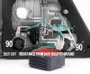
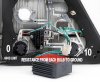
If I wire up a 6W bulb to the grey/yellow tail light wire (power source)would this plus the LEDs (I would think about 1.5 watt) fool the OBC and stop the error message? The resistors are big (see photos), I dont know why the left hand one doesnt heat up as much as the right one, as they both are the same lights
Users who are viewing this thread
Total: 1 (members: 0, guests: 1)
Similar threads
- Replies
- 12
- Views
- 958
- Replies
- 0
- Views
- 650