• The Forums are now open to new registrations, adverts are also being de-tuned.

Jacksh!t.

Bellow

Hardcore MB Enthusiast
Joined
Apr 26, 2010
Messages
10,342
Location
Ecosse.
Car
C2500 350, 450
'Build it and they will come' is one expression. 'Give the people what they want' another. But if the people won't say what they want....
I've been asking questions on the tail end of this thread >> Safe use of jacks | General Discussion with little response hence a new separate thread for some answers.
I'm in the process of designing a piece of kit for vehicle lifting and support which will be better than the jack/stand in the photo I posted and guaranteed better than anything you are currently using this side of post ramps.
What I need to know though is the preferred option for where the jack and/or stand meets the vehicle. Principally, I need to know whether you use the edge of a welded seam (AKA pinch welds) or, have an even horizontal surface that bears the weight when jacking/supporting at the sills. My assumption so far is that jacking to axle stand height is done at a single point (eg, under diff) and requires full height to be attained that way. Some questions then.
  1. Is lifting at the seam unavoidable and if so, are you happy for the seam to take the load or do you want/use some slotted intermediate to bypass the seam and contact the horizontal surfaces higher up either side of it?
  2. If lifting is on a flat horizontal surface (eg, designated jacking pad) do you insist on some non-metallic intermediate (eg, hockey puck) or are you happy with metal to metal?
  3. Is a hybrid of the above acceptable eg, lifting with metal to metal but axle stand support being non-metallic?
  4. Is there a need for the traditional U shaped lift point of the type used for true axles?
  5. Is there a desire for the axle stand to be placed under the sill prior to any lifting and if so, what is the height available (between sill and ground) for that?
  6. Would you prefer single, designated lifting point or, it be supplied with alternative lifting points that can be removed/fitted depending on the vehicle's requirements
  7. Any other aspects/features you would want incorporated?

In prospect here is a device that will more safely lift a vehicle to height for working underneath it and will lock as positively (physically) as an axle stand with its wide stable base. If sized to slip under the sills of an unlifted vehicle they will be a very easy way to lift the tyres free from the ground thus reducing the risk of flat-spotting tyres on vehicles that are in storage. To outline but two of the potential uses.
I intend manufacturing these to sell but I need to know what is wanted so please give me some guidance here. Whatever lifting and support methods you are using there is a better solution available - your opportunity to tailor it your exact requirements is here. TIA.
 
The biggest issue I can see is that "one size doesn't fit all".
Personally I hate metal-to-metal contact when jacking cars up, so I tend to use pucks.
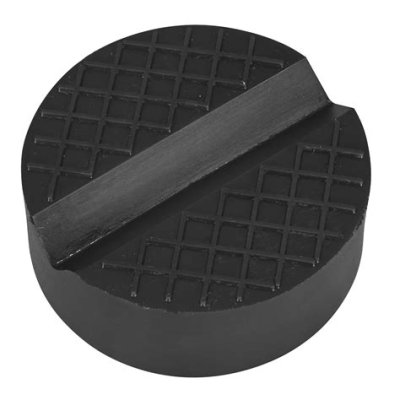
Our Leon has pinch weld points - if I'm using the trolley jack I've got one of these (the emergency jack that comes with the car has a v-groove in the saddle to fit the pinch weld) :
th-1912588076.jpg
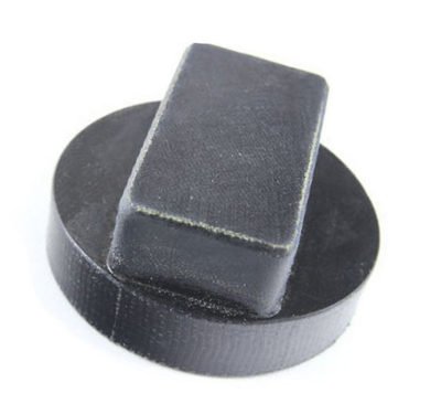
The 3 Series has rectangular plastic jacking points which always get destroyed when using anything other than a BMW jack. It's a rubbish design (even though you can replace them relatively easily). For that I have these:
manufacturer-of-rubber-bmw-jack-pad-for-floor-jack-car-400x366-4204129279.jpg
The main issue with the BMW is there's only about 13cm clearance under the sill extensions when the car is sitting on a level surface.
 
Thanks SM - appreciated.

The biggest issue I can see is that "one size doesn't fit all".
True, but the extent of the variation is as yet unknown.


Personally I hate metal-to-metal contact when jacking cars up, so I tend to use pucks.
Our Leon has pinch weld points - if I'm using the trolley jack I've got one of these (the emergency jack that comes with the car has a v-groove in the saddle to fit the pinch weld) :
View attachment 158876
In either case - puck or Seat jack - the weight is borne on the edge of the pinch weld/seam - as opposed to the horizontal surface - Y/N?
It appears that away from the OEM jack, a trolley jack is the jack of choice and a puck is preferred as otherwise the 'claw' pad of a trolley jack makes contact at only two points and that could potentially overstress the pinch weld/seam. From other research, it appears that the designated portion of the pinch weld/seam for lifting is marked with cut-outs. Thus, if a jack is to be used to lift the vehicle and axle stands be placed under the sill then there isn't an OEM approved section of pinch weld/seam available.


The 3 Series has rectangular plastic jacking points which always get destroyed when using anything other than a BMW jack. It's a rubbish design (even though you can replace them relatively easily). For that I have these:
View attachment 158878
I saw that type. Do you know if that is BMW specific and that most other cars' lift points are of the pinch weld/seam type?


The main issue with the BMW is there's only about 13cm clearance under the sill extensions when the car is sitting on a level surface.
So far, the minimum clearance required appears to be circa 145mm - but possibly more if a puck is required.
So, for anyone interested in this and wanting to be able to place a jack/axle stand under a sill without any prior lifting my questions are what height is available and what is required in the way of a puck/lift pad/etc?
For those intending serious work on their car who would raise the car to axle stand height with a trolley jack, what height do you want the jack/stand to be - ie, what height do you set your axle stands at?
 
My current car and my previous MB use the BMW type fitting, but I tend to use a flat rubber plate on my trolley jack on my current car due to the clearance under the sill.
Personally I detest jacking on seams as its easy to fold them if the jack isn't square.
 
  1. Is lifting at the seam unavoidable and if so, are you happy for the seam to take the load or do you want/use some slotted intermediate to bypass the seam and contact the horizontal surfaces higher up either side of it?
  2. If lifting is on a flat horizontal surface (eg, designated jacking pad) do you insist on some non-metallic intermediate (eg, hockey puck) or are you happy with metal to metal?
  3. Is a hybrid of the above acceptable eg, lifting with metal to metal but axle stand support being non-metallic?
  4. Is there a need for the traditional U shaped lift point of the type used for true axles?
  5. Is there a desire for the axle stand to be placed under the sill prior to any lifting and if so, what is the height available (between sill and ground) for that?
  6. Would you prefer single, designated lifting point or, it be supplied with alternative lifting points that can be removed/fitted depending on the vehicle's requirements
  7. Any other aspects/features you would want incorporated?
Just speaking from my own experience when using jacks on other peoples cars...

1. I never jack up on the sill, always go to a subframe mounting point in the front and the diff/axle in the rear. I have a few low height/long reach jacks for this, an added bonus with them is that they can lift over 3 feet high due to the arm length.

2. Always on a rubber pad, purely to stop the jack head sliding about.

3. See above.

4. I think the U shape is not needed on modern cars, it was mainly so the sill pinch weld would sit in it on older vehicles. A set of flat top stands is more appropriate.

5. Stands wont need to be under the vehicle until the desired height is reached.

6. Interchangeable heads would be a good idea, the BMW type in post 2 is a good example.

7. Whatever jack you use make sure it has a "quick lift" built in.
 
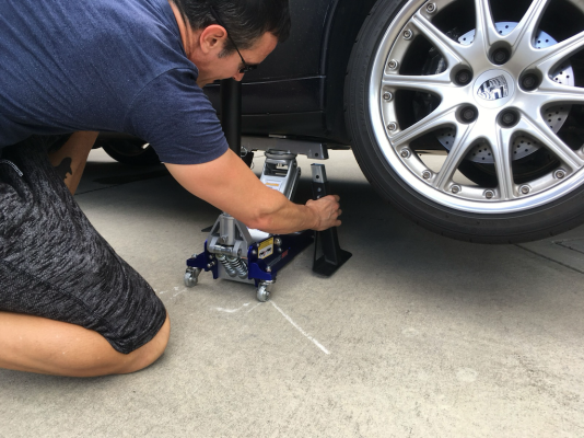
I think it was someone on this forum who posted this photo - it looks like a really good solution. It's a piece that fits between the jacking point and the trolley jack, so that you can jack the car with it in place, then fit the adjustable legs (to turn it into a stand) and then remove the trolley jack. I looked to buy a pair of these, but they only seem to be available in the US. If you can make something along these lines I'd be interested in buying them.

jack stand 1024.png

My W221 has the plastic recesses that the factory jack inserts into. The distance from the ground to the lower lip of the plastic recess, i.e. effectively to the underside of the sill, is ~140mm at the front jacking point, and ~150mm at the rear. But of course I can raise the suspension on my car, so something a little taller than that would work in my case.

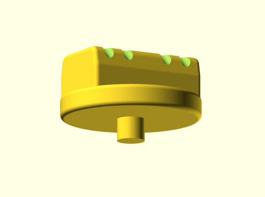
I have made some 3D models based on the profile of the factory jack (Printables) for pucks that fit to the top of a couple of trolley jacks and also to the top of an axle stand. I've printed these in ABS with 100% infill and they are remarkably strong. I use them to lift my car with a trolley jack at the factory jacking points, but then I do struggle to get an axle stand underneath somewhere.

Mercedes Jack Adapter - Disc.png

Mercedes Jack Adapter - Jack.png
 
Last edited:
Thanks for the additional posts since I last posted - all helpful and appreciated.
Now, back to the questions...
Material choice: SpikeyMikey's puck for pinch welds - is that plastic or vulcanised rubber? If the latter, is there noticeable deformation in use? Clearly, no one is fond of steel on steel but given the choice of a hard plastic (eg ABS) or vulcanised rubber - is there a preference? On the face of it looks like the hard plastic would be stronger but slippier, the converse true for vulcanised rubber. Thoughts?

SpikeyMikey's BMW puck and ChrisPDuck's ABS pucks - how snug a fit in the receptacle affixed to (BMW and MB) chassis is it? What has occurred to me is that virtually all the OEM jacking provisions are for post ramps where the lifting is vertical and, a 'square lift' whereas we are jacking at corners where the vehicle inevitably tilts. Thus, when jacking from one side, the vehicle and puck are no longer at 90 degrees but must assume an angle. I can see that the V slot in a puck for use with a pinch weld can easily accommodate that but it's not immediately obvious that one for the receptacle type can. Where then is the movement to permit that? Between the puck and receptacle or between puck and jack?

I'd forgotten about the Renn Sport cradle. IMO a reasonable (if somewhat costly) solution - that I think I can better.
Both of mine are rubber and yes the pinch weld one has marked up unsurprisingly.
The secret to the BMW one isn't the material, so much as the raised portion should be sufficient that the puck bottoms out in the receptacle and doesn't just bear on the edges.
 
SpikeyMikey's BMW puck and ChrisPDuck's ABS pucks - how snug a fit in the receptacle affixed to (BMW and MB) chassis is it?
I modelled the printable puck to be as close as possible to the head on the factory jack, and the fit is such that there's very little wobble in the receptacle. The issue of the changing angle would apply just as much in the case of the factory jack, so I'm not really sure how that resolves in practice. There does seem to be a bit of movement of the receptacle itself within the sill - maybe that's designed-in to accommodate the changing angle, but I doubt it somehow.

The secret to the BMW one isn't the material, so much as the raised portion should be sufficient that the puck bottoms out in the receptacle and doesn't just bear on the edges.
This is the same for the Mercedes factory jack/puck - the top of the head/puck bottoms out before any pressure is put on the edges of the receptacle. Unlike when a tyre place uses their trolley jacks under those receptacles - which usually results in some deformation of the receptacle!

I'd forgotten about the Renn Sport cradle. IMO a reasonable (if somewhat costly) solution - that I think I can better.
I'm genuinely pleased to hear this!
 
Both of mine are rubber and yes the pinch weld one has marked up unsurprisingly.
The secret to the BMW one isn't the material, so much as the raised portion should be sufficient that the puck bottoms out in the receptacle and doesn't just bear on the edges.
Just been having another look at a video of a guy making pucks for a BMW >>
To view this content we will need your consent to set third party cookies.
For more detailed information, see our cookies page.
and my conclusion - pretty much confirmed by you - is that the receptacle is as much a sign saying 'jack here where there's solid metal above'. That said, it seems its edges are strong enough to bear the weight - but do get damaged doing that. In the video, the guy's pucks which, in fairness, I can't really fault, do distort at the edges.
My current conundrums are, for the receptacle type whether the elasticity inherent in the vulcanised rubber ones is sufficient to allow for the tilt as the vehicle lifts and better than a hard plastic one which I suspect would need a bit of side clearance. What I'm up against is a wish to have the base of the jack as per that of an axle stand the consequence of which is that the entire lifting apparatus remains absolutely vertical while the vehicle tilts as lifted. I found an old mechanical type bottle jack and its base is curved to compensate for tilt.
Also, for pinch welds where instead of lifting with a trolley jack from the side where the tilt of the vehicle is around a longitudinal axis which suits the V slot the lifting is done such to lift one end of the vehicle (rotating around a transverse axis) and if a hard plastic puck would lead to (potentially damaging) point contact where the flexibility of vulcanised rubber would maintain more consistent contact. Minute details I know, but as ever, the devil is in the detail - and given the task, it all has to work perfectly.

As it stands (sorry!) I'm veering toward the hard plastic for the receptacle type, vulcanised rubber for the pinch weld type and for where jacking is in a plain horizontal surface where the additional over hard plastic flexibility and grip respectively are of use.

Still trying to gauge the attractiveness - or otherwise - of not having to jack to full height from a single point (eg, diff) to achieve final axle stand height. For sure not many will be as keen as carat 3.6 to jack 3 feet (not disparaging carat 3.6 here - he clearly knows what he is doing). I just know that jacking in that manner (complicated by being outside on less than perfectly even ground) stresses me out.
 
I'm genuinely pleased to hear this!
I think what I'm working on will suit you exactly and the reason for that is your ability to lift the car a touch on its suspension. If my jack has to slip under a sill with the car unlifted its lift thereafter will be circa 100mm. Enough probably for wheel removal for hub/brake work etc and for tyre preservation on a laid up car but for lifts greater than that (eg, getting right under the car) the car will have to be lifted by a small amount as the jacks to attain the additional height will have to be taller - hence my continual questions about how high are people comfortable with with single point jacking and what height do they want when on stands.
 
Is 100mm sufficient to lift the wheel off the ground? I know it always seems to take a lot of lifting to take up the suspension travel, but I've never actually measured it.
 
Is 100mm sufficient to lift the wheel off the ground? I know it always seems to take a lot of lifting to take up the suspension travel, but I've never actually measured it.
Good point - noted.
 
This is the same for the Mercedes factory jack/puck - the top of the head/puck bottoms out before any pressure is put on the edges of the receptacle. Unlike when a tyre place uses their trolley jacks under those receptacles - which usually results in some deformation of the receptacle!
All four receptacles on mine when I bought it were badly chewed up, to the extent that any further use would probably have caused metal to metal contact between jack and underbody. An easy and cheap enough fix to replace them thankfully.
 
Is 100mm sufficient to lift the wheel off the ground? I know it always seems to take a lot of lifting to take up the suspension travel, but I've never actually measured it.
In all probability 4'' is not enough (I can hear the voice of the actress addressing the bishop in my head). I had a long look last night and at my design(s) and the initial height appropriate to sliding under a sill will only provide 100mm/4'' of lift. A taller unit would provide 120mm of lift but requires initial lifting - which is where I thought it might be advantageous but there isn't the concern I anticipated re lifting at a single point (eg, under diff) and my view on that was clouded by the acute difficulty with that aspect when I worked on my fortwo (very short wheelbase). Missing that 100mm was insufficient is likely due to me having a rear axle (Suburban) that when I lift has only the sidewall deformation to overcome to raise wheels clear of the ground. Maybe I'll build some specifically for lifting the 'Burb but as a commercial venture, it ends here.

Clearly, only trolley jacks (my designs were to utilise bottle jacks) provide sufficient lift and it's hard to conclude anything other than the Renn Sport design is viable. It is probably patented so no possibility of producing in serious numbers by anyone else. An alternative design - eg, a plate twixt jack and vehicle with pivoting (or slotted into) legs which are then braced to provide a stable tri/quadpod might work but there are a number of difficulties associated with the variation in heights necessary.

To address ChrisPDuck's directly desire for a viable solution my suggestion is to show photographs (but not the price!) to a competent blacksmith and ask for them to copy the design. As a one off for personal use you needn't worry about IPR.

If a better idea deploying trolley jacks arrives in my head (unlikely) I'll bring it here but asphyxiation awaits anyone holding their breath while waiting.
Thanks to everyone who participated here. Your inputs are greatly appreciated. At the very least you have saved me diving down an unproductive rabbit hole - thank you.
 
I'm sorry to hear this, but I understand the issues. The next time I have to take a wheel off I'm going to measure how much lift is actually required for the tyre to come off the ground.

Regarding the RennStand design, they give the impression of having gone out of business - not a single item in stock, no new news since last Autumn - but of course that fact would not affect their patents in any way. However, I note that their patents are all US patents - would that prevent someone outside the US from marketing something similar?
 
I'm sorry to hear this, but I understand the issues.
Thanks. The issues took a bit of uncovering but once obvious....
The next time I have to take a wheel off I'm going to measure how much lift is actually required for the tyre to come off the ground.
Yes, that could be a help. Even if 100mm lifts the wheel enough for removal the car is still somewhat low to be working on. It could though be enough for tyre conservation during lay up. Chances are such a car is a sportscar with even more restrictive ground clearance!
Regarding the RennStand design, they give the impression of having gone out of business - not a single item in stock, no new news since last Autumn - but of course that fact would not affect their patents in any way. However, I note that their patents are all US patents - would that prevent someone outside the US from marketing something similar?
I honestly don't know the patent situation but absolutely if you commission a blacksmith/fabricator to copy the design there will be no blowback for a one off. I might even consider doing that in greater numbers but, given the predominately welded construction I'd have to farm that out and the cost of that is likely prohibitive. When I was working on my designs I was conscious of keeping construction within my skill-set with any farmed out welding or machining being minimal and to that end discussed it with an engineer highly proficient in welding and machining. If he asks me how I'm getting on I'll introduce him to the Renn Sport design and see if he bites...
 
Not done yet....
 

Users who are viewing this thread

Back
Top Bottom