• The Forums are now open to new registrations, adverts are also being de-tuned.

Rover P6 front roll centre

Bellow

Hardcore MB Enthusiast
Joined
Apr 26, 2010
Messages
10,770
Location
Ecosse.
Car
C2500 350, 450
Does anyone know how to go about ascertaining the roll centre height of a Rover P6's front suspension?
I already know the answer (7'' above ground level) but not the method. Is the (leading) top arm/wishbone viewed as a conventional wishbone of infinite length?
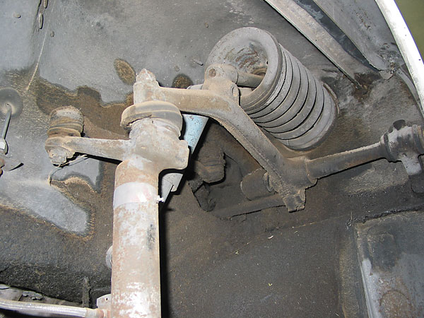
Rover3500S-FS-D.jpg
 
Strange request on a Merc forum.
I’m sure someone on the Rover forums may be able to help.
Loved my first P6, a 1967 2000TC I was only 21 when purchased it back in 1971
 
I had quite a few P6's a 2000TC annual and a V8 3500s manual.. I did virtually every job on them but never had to do anything with the front spring area sorry!
 
My question isn't specific to the Rover P6 - it's a theoretical question as to how to treat geometry that includes a leading/trailing member in the linkages in ascertaining roll centre locations.
The P6 front suspension was chosen as an example of such an arrangement.
 
Variation on the theme.
Trailing and leading arm suspensions have roll centres at ground level. Roll centre location for semi-trailing is derived via a plan view and then end elevation view - that much is well documented. What of a pure trailing arm set-up (where in plan view the pivot axis is normal to the cars longitudinal axis) but in end elevation view that axis is skewed? Any ideas how that is dealt with to ascertain roll centre location?
 
A little more on P6 suspension.
Rover P6 Design Innovations, by Bill Wardlow

I'm afraid I cant answer your question because I can't exactly visualise what you are asking. :oops: Its one of these problems that probably needs visual aids such drawing boards, diagrams, pinboards and tape to make sure we are all talking about the same thing? ;)
 

Cheers - but I saw that - and nicked the photo from there too!

I'm afraid I cant answer your question because I can't exactly visualise what you are asking. :oops: Its one of these problems that probably needs visual aids such drawing boards, diagrams, pinboards and tape to make sure we are all talking about the same thing? ;)

Roll centres are (or can be) tricky. It's all about the convergence points of the linkages that provide lateral location for the hub and is relatively straightforward when the links lie across the car but trickier when they are longitudinal to the car's main axis.
The more recent question is easily visualised by considering looking at the rear suspension of an Issigonis Mini from the rear of the car. The axis (spindle) the swing arm pivots on is horizontal. What if it wasn't? If the inner end of the spindle were higher that the outer end? Or vice versa? Where is the roll centre in that situation - still at ground level or somewhere else? That's what I'm trying to nail down (in the later question that is).
 
This taken from Design for Competition 3RD EDITION 750 MOTOR CLUB PUBLICATION
OUb0Xaw.jpg
 
This taken from Design for Competition 3RD EDITION 750 MOTOR CLUB PUBLICATION
OUb0Xaw.jpg

That's the type of thing I've been wading through lately - Mallock, Costin & Phipps, etc.
The problem as I see it is that those articles were written at a time when swing axles were being replaced by double wishbones and solid axles still prevailed. Wishbones have become the racing 'standard' so all the literature has featured transverse linkages only (axles included). There would have been a time when my question(s) could have been answered by anyone who had ever been tasked with computing a roll centre location but subsequently with the focus on wishbones, that knowledge appears to have been lost.
Someone knew how to locate (in space) the P6's roll centre - but in 2019 a (say) F1 championship winning car can be built knowing only wishbones. I doubt that I'm going to get an answer to this short of a seance with Spen King.
 
Thanks Grober - but again no guidance on unorthodox leading/trailing link set-us.
But, the pic below (from linked site) is I think an adjustable rear suspension (referred to as 'beam' though it isn't) for an Issigonis Mini and possibly the inner pivots are used to adjust camber - thus inclining them in end elevation. An avenue to pursue then as if correct, surely someone will have observed effects attributable to other than camber. Ditto the use of adjustable camber brackets.
(If anyone thinks this mish mash of knowledge on what should be well understood systems is a bit odd, wait until you find out how wide of the mark the accepted wisdom on branch exhaust manifolds is).
trailing%20arm.jpg
 
Ditto the use of adjustable camber brackets.

So, a cursory glance on the 'net and I find this >> Suspension - Basic priorities and within it this:
''However, what is not often appreciated/known is that increasing rear negative camber has a two-fold positive effect. First, it raises the rear roll centre from ground height – anything gained here helps to counter skewed rear roll as the front roll centre is much higher – and second it causes the outer wheel to go progressively toe-out when cornering''

The 'toe out' part I concur with (a model I have made exhibits this tendency) but lowering of the roll centre? Maybe it's just counter intuitive to believe that the motion (at the hub) being inward toward the car's centreline helps resist roll and it is correct. But, going in the other direction (which in this application would increase positive camber) should then lower the roll centre accentuating the roll tendency and definitely that seems wrong!
More research required....

(On the plus side, I think I've finally nailed an elusive intuitive understanding of how and why roll centres create the weight transfer they do. It's all in the H term - thank you Mr Mallock).
 
So while all this may sound a trifle esoteric for many reading this thread the advisability of running a degree of toe in on rear suspension to aid stability goes some way to explain why many Mercedes models experience excessive rear tyre wear on the inner edge of their tread .:dk:
 
So while all this may sound a trifle esoteric for many reading this thread the advisability of running a degree of toe in on rear suspension to aid stability goes some way to explain why many Mercedes models experience excessive rear tyre wear on the inner edge of their tread .:dk:

Toe in though, should knock out the outer edge...
(I suspect in the case you mention that camber compensation on bump (to keep the wheels upright during cornering roll) is the cause when accelerating hard in straight lines).
 
Thanks Grober - but again no guidance on unorthodox leading/trailing link set-us.
But, the pic below (from linked site) is I think an adjustable rear suspension (referred to as 'beam' though it isn't) for an Issigonis Mini and possibly the inner pivots are used to adjust camber - thus inclining them in end elevation. An avenue to pursue then as if correct, surely someone will have observed effects attributable to other than camber.Ditto the use of adjustable camber brackets.

This question is currently being forwarded to the only 'someone' I can think of who can answer it. When the reply arrives.....
 
OK, what should be a simpler question - given it relates to a double wishbone set-up.
Normal method of locating roll centre location with double wishbones is to draw lines though the outer and inner pivots for each arm, extend the lines until they meet, and from that point back toward the centreline of the car to meet the tyre contact patch. Where that line crosses the car's centreline is where the roll centre is. All fine and well
But what if the convergence of the lines is on the other side of the car, ie, doesn't cross the centreline? An example would be, say, a lower wishbone parallel with the ground and an upper wishbone inclined downward from its inner pivot to its outer pivot. There, the point of convergence is on the same side as the wishbones and when drawn back to the contact patch, does not cross the centreline so no plot point. Where is the RC in that situation?

Below ground level is the answer. How far below is ascertained by drawing a line from the converged wishbone lines back through the tyre contact patch and where it intersects the car's centre line is where the RC is.
 

Users who are viewing this thread

Back
Top Bottom