• The Forums are now open to new registrations, adverts are also being de-tuned.

Testing for broken wire

DamoC43

Active Member
Joined
Oct 28, 2023
Messages
82
Location
Nottingham
Car
C43 Estate
Wondering if anyone can advise.
I've a fault on the car (C43 S205 2019) which i believe is most likely caused by a damaged wire(s) somewhere in the loom to the front bumper loom. I've had to join some broken wires back together using solder sticks on this loom. I want to be able to test for continuity from the front bumper loom connection plug, which clips onto front bumper, back up past the repair work. The only way i have of doing this at present would be to cut the wires nearer the car above the repair and test for continuity back at the front bumper connection plug. This is something i'd like to avoid if possible since it will result in even more repaired wire joints on wires that already have a repair.
I was wondering if i could perhaps locate where this loom (Front parking sensors and pedestrian protection sensors) terminate at a fuse box location? Or is there some other non destructive way i can perform this test? wire pinning?

Many thanks
 
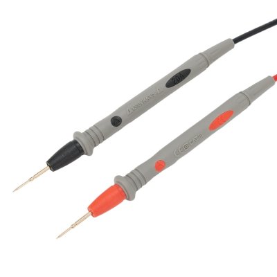
Piercing probes are great for this sort of thing
These are the originals, but cheap copies are available everyehere


Back pinning probes are useful too

 
Piercing probes are great for this sort of thing
These are the originals, but cheap copies are available everyehere


Back pinning probes are useful too

Great shout, just oredered some due in tomorrow. In the mean time i've just experimented with stabbing a sewing needle through the solder stick and it works. 1st wire is ok, has continuity all the way back to the sensor plug.
If it turns out not to be a broken wire, what else could give a fault code description of 'short to positive or open circuit'. This error message relates to one of Two pedestrian protection sensors. Actual fault code is B273715. The only other thing i can think of is the sensor itself which would be a surprised given its a brand new OEM part.
 
I’ve seen these with bad wires on the bumper side of the plug, close to the large plug. They go green inside the insulation. I have repaired them before, but a new bumper loom is the best answer
 
Piercing probes are great for this sort of thing
These are the originals, but cheap copies are available everyehere


Back pinning probes are useful too

The advantage of the Fluke type being you can't spear your fingers with them:rolleyes:
 
I’ve seen these with bad wires on the bumper side of the plug, close to the large plug. They go green inside the insulation. I have repaired them before, but a new bumper loom is the best answer
The repair is not on the bumper loom otherwise i'd have just replaced the lot, it's on the spur of the main loom which leads upto that plug you mention. I asked an independent Merc garage today how much to replace - £1100 and a 3 month lead time.......so we ain't going down that route
 
Well i thought i'd cracked it, tested for continuity on the second wire after the rain stopped and no signal so cut and replaced the original repair and tested again back to plug and all good. Put all back together, scanned car and still got same error. So i suspect there may have been damaged wires even higher up the loom. When my pierce probes arrive tomorrow i'll be able to test the loom much higher than the crash damage and hopefully find something wrong. I'll keep you updated
 
Are unplugging from the end device, to eliminate the meter seeing a loop in parallel?
 
Are unplugging from the end device, to eliminate the meter seeing a loop in parallel?
The only part i've unplugged is eithe the main loom link at front bumper or the two pin plug off the sensor itself. So far i've been testing individual wires.
 
Great shout, just oredered some due in tomorrow. In the mean time i've just experimented with stabbing a sewing needle through the solder stick and it works. 1st wire is ok, has continuity all the way back to the sensor plug.
If it turns out not to be a broken wire, what else could give a fault code description of 'short to positive or open circuit'. This error message relates to one of Two pedestrian protection sensors. Actual fault code is B273715. The only other thing i can think of is the sensor itself which would be a surprised given its a brand new OEM part.
Water ingress somewhere ? Particularly inside the bumper .
 
Well i thought i'd cracked it, tested for continuity on the second wire after the rain stopped and no signal so cut and replaced the original repair and tested again back to plug and all good. Put all back together, scanned car and still got same error. So i suspect there may have been damaged wires even higher up the loom. When my pierce probes arrive tomorrow i'll be able to test the loom much higher than the crash damage and hopefully find something wrong. I'll keep you updated
Crash damage ?
 
Crash damage ?
Yes it's a cat s repair project. If you've a spare hour you can read what's becoming my diary click>> here inc some photos :)

Ref water ingress, the sensor is brand new oem part from merc. The bumper has been fully rebuilt and has spent the last 2 months in my house while i wait for he car to come back from paint.
I've pinned the wires up near the bulk head and still get continuity at the sensor plug.
So I thought perhaps it's the plug itself, which has been replaced. Perhaps i get continuity but the resistance is out of spec due to the repair joint. So i got the old original sensor, checked it does not cause the code using the left hand side and then hard wired it into the loom plug but still get the fault!! I'd also swapped the sensors over from left to right but still get the same error.

So it's not the sensor, plug or a broken wire. What else can it be?
It's not likely to be a code my scanner can't clear since i can replicate the code and clear it by plugging and unplugging the left hand one.
So i'm pretty stuck now. My last hope is that this code is somehow being influenced by the other code related to the gas cylinder code B280613. Replacement part for this code was due yesterday but hasn't arrived yet so i doubt i can continue now until next week as i'm away Mon to Fri with work. This feels like wishful thinking though but worth ruling out before i waste money on something else.

My last theory is that it's resistance related. My hard wire test probably increased resistace as the wires i used were very thin. Might try it again today with thicker wire?

I could also change the front bumper loom but i can't see this solving anything if i'm already getting continuity to the sensor plug?
 
I'm not familiar with this particular sensor, but can give some generic fault finding tips.

Testing for continuity is ok when you know you've got a signal at point A, but not point B. I don't think you are in that position though?
Going in blind when you don't know the route, both endpoints or what that signal looks like is more difficult. Have you looked at getting a wiring diagram?

It's still possible to do it the hard way as you do have the other sensor though to use a reference.So I'd be trying to identify the signal on each of the pins ( is it 2 or 3?) on that good side. Then go back to the bad side and see if you are you missing one or more. I say signals, but without knowing what they are, are they could be powers, grounds, PWM, analog (doubt), or other. The number of pins would help identify the possible signal type used.

If you only have a multimeter this may prove difficult, but may still be possible. Oscilloscope would be best but wouldn't suggest you go this route if you're not confident with electronics (think I read in your other thread you're not). Even with a a meter on DC volts range, if the signal is a PWM you'll get some thing which helps identify the circuit. Some meters even have a duty cycle and frequency setting.
You should try this with the sensors disconnected and connected.

The fault description, short to positive or open circuit is basically saying the module is seeing a high signal on that pin, 5v or above. The fact it doesn't know if a short or open will be because the pin is pulled up internally to a supply voltage (5V I expect). All signal pins will be either pulled up or down to ensure that they are in a known state during an open circuit condition.
So if the pin is at 5v, any wire attached to it should be at 5v. So that is something you can check for.

Something else to consider, it is quite possible that the connection between this signal pin and the sensor is completely intact. For the sensor to work though it would need at least one other connection, a ground and possibly even a power. So is this what is causing that fault?

Good luck.
 
That may be more important than you'd think! I have no idea whether this story is true, but it seems like it could be: 1999 Darwin Award: Resistance is Futile
:eek:
I use a pair of these to buzz out the Samtec 1.27mm pitch connectors we use on certain jobs
a2b6d0d95f1d5eac2943ba062f8350f5.jpeg
They are pretty much like hypodermic needles.
 
A couple of things wrong with the theory.
While current from one thumb to t'other will mean current passes through the heart, there will be parallel paths through he body. This will reduce the actual current that passes through the heart.

I don't have one of the said Flukes, but tested the voltage of one DVM (set to measure resistance), with another (set to measure DC voltage). The output of the meter is a fraction over 1 volt.
That's no surprise as when testing delicate electronics you wouldn't want to be sending 9 volts through it.

For the same reason you wouldn't want the meter to pass a significant current through a delicate circuit. I recorded less than 2 micro amps, that's at a circuit resistance of 1.5 ohms, less than I could ever expect a bodies resistance to be, from thumb to thumb at least.

Since I don't have an apprentice who's thumbs I can stab, I'll wait for Mrs Me to get back from earning the Guinness tokens.

If you don't hear from me again it's because it flippin' hurt her and I'm in hospital.
If you do it'll be while I'm taking a break from digging a 5'7" hole in the garden, but I reckon I'll be in hospital tbh.
I'm sure you're right, but note that the meter mentioned in the article is an analogue meter, and according to the manual (https://simpsonelectric.com/wp-content/uploads/File/manuals/Manual-260-8.pdf), the 'R x 10,000' resistance setting does indeed use 9V. But I think the 'nominal short circuit current' of 75µA is the maximum? Maybe earlier models didn't have the same limit? Anyway, even if the story isn't true, it was interesting to read about the '1-10-100' rule.

EDIT: Good luck with your experiment!
 
  • Like
Reactions: m80
That may be more important than you'd think! I have no idea whether this story is true, but it seems like it could be: 1999 Darwin Award: Resistance is Futile
Hmm...

I'd be inlined to put the meter across an ammeter and see what sort of current it can push out into a short circuit .

More of a danger to people messing around with HT leads on a car whilst running .
 
I'm not familiar with this particular sensor, but can give some generic fault finding tips.

Testing for continuity is ok when you know you've got a signal at point A, but not point B. I don't think you are in that position though?
Going in blind when you don't know the route, both endpoints or what that signal looks like is more difficult. Have you looked at getting a wiring diagram?

It's still possible to do it the hard way as you do have the other sensor though to use a reference.So I'd be trying to identify the signal on each of the pins ( is it 2 or 3?) on that good side. Then go back to the bad side and see if you are you missing one or more. I say signals, but without knowing what they are, are they could be powers, grounds, PWM, analog (doubt), or other. The number of pins would help identify the possible signal type used.

If you only have a multimeter this may prove difficult, but may still be possible. Oscilloscope would be best but wouldn't suggest you go this route if you're not confident with electronics (think I read in your other thread you're not). Even with a a meter on DC volts range, if the signal is a PWM you'll get some thing which helps identify the circuit. Some meters even have a duty cycle and frequency setting.
You should try this with the sensors disconnected and connected.

The fault description, short to positive or open circuit is basically saying the module is seeing a high signal on that pin, 5v or above. The fact it doesn't know if a short or open will be because the pin is pulled up internally to a supply voltage (5V I expect). All signal pins will be either pulled up or down to ensure that they are in a known state during an open circuit condition.
So if the pin is at 5v, any wire attached to it should be at 5v. So that is something you can check for.

Something else to consider, it is quite possible that the connection between this signal pin and the sensor is completely intact. For the sensor to work though it would need at least one other connection, a ground and possibly even a power. So is this what is causing that fault?

Good luck.
Great reply @Supernoodle very detailed and helpful.
 

Users who are viewing this thread

Back
Top Bottom