• The Forums are now open to new registrations, adverts are also being de-tuned.

Using piggyback fuse

Gollom

Hardcore MB Enthusiast
SUPPORTER
Joined
May 10, 2006
Messages
10,133
Location
Preston, Lancs
Car
S204 C220CDi Sport ED125 (Mr) Kia Picanto Domino 1.1 (Mrs)
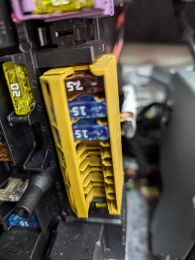
Will be using one of the below for my reversing cam (into Fuse position 73) The existing fuse is 15a and I think Richard suggested a 5a fuse for the camera given the wire thickness. Which fuse goes where in the piggyback please? Thanks

71qahNYDHCL._SL1500_.jpg
 
Just make sure you plug it in the correct way round.
To view this content we will need your consent to set third party cookies.
For more detailed information, see our cookies page.
 
Just make sure you plug it in the correct way round.
To view this content we will need your consent to set third party cookies.
For more detailed information, see our cookies page.

Still Chinese I'm afraid. Do you have an answer for a Bear of Very Little Brain please? Cooking & computers, I'm your man. But auto electronics......
 
Looking at those pics…
Plug it in with the red cable at the fused side of the fusebox - i.e. with the original fuse out, the red cable goes to the ‘dead’ side ofthe original fuse. If that makes sense.
Original vehicle fuse plugs in to the two connectors that are furthest from the red wire.
New circuit fuse plugs into the connectors that are nearest to the red wire.
N.B. Those two add a fuse connectors are different and can add to the confusion.
So if I keep the orientation of the fuse I take out? All so confusing! LOL
Well spotted - they ARE different. How odd!
 
Just to confuse things even further :

Anytime i am adding something extra to a vehicle i just pick up the supply from an unused fuse connection in one of the fuse boxes , there will be unused constant live or ignition live in most vehicles that can be used.

A crimp on spade connection with an inline fuse pushed into the live side of a connection has done the trick on many occasions with no need to put any extra load onto an existing circuit.

K
My brain has just melted
 
There’s no orientation as such 👍🏻👍🏻
With the fuse out, one connector will be live on aux or ign - whichever circuit you have chosen and the other will not.
When you plug in the add a fuse, the red wire should be on the side of the fusebox connector that wasn’t live.
Then put in the original fuse into the socket (two spade connectors) which isn’t the one with the red wire (bit of negative logic here!) and the original controlled circuit should come back live. Put the new 5 amp fuse into the other circuit WITH the red wire and tour ‘new’ circuit should become live (and be protected)
Or do what Kenny does, which is my preferred option if there is a spare slot available in the fusebox. 👍🏻👍🏻👍🏻
 
Picture of my rear fuse box. The one I intend to piggyback from is the bottom 15a one 71 (Front cigarette lighter with ashtray illumination - Front vehicle interior power outlet) Car is a S204 2011

Unless I am advised differently of course! LOL
 

Attachments

  • PXL_20240716_162145919.jpg
    PXL_20240716_162145919.jpg
    235.2 KB · Views: 4
That’s the circuit I would probably use. But I would be testing out those ‘spare’ slots with a testlight in conjunction with a fuse diagram and using Kenny’s method if one was available.
Just to keep things simple.
 

Users who are viewing this thread

Back
Top Bottom