Navigation
Install the app
How to install the app on iOS
Follow along with the video below to see how to install our site as a web app on your home screen.
Note: This feature may not be available in some browsers.
More options
Viano / Vito 2012 W639 Electric Sliding Door Lock Issue. Possible Solution
- Thread starter NotAT5
- Start date
Ok so this morning I grabbed me trustey meter and went to check & Confirm that the micro switch is still playing up .. and now it's working again .. bloody thing anyway let's confirm the pins and the contact switch so this video is just to show the door contact switch and pins
Door contact switch and Pins
Door contact switch and Pins
Ok I've been trying to replicate the faulty side door.... To no avail,
and now i'm wondering if the Micro switch ( IN MY CASE ) is / was faulty because for the last few days its working fine ?
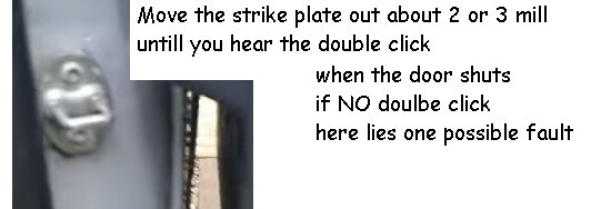
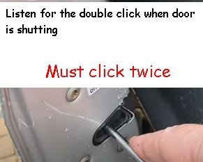
what I did was to move the strike plate outwards a little and or twist it a millimeter so that when the door shuts we in fact do get the DOUBLE click.
I only did this as I had what is known to be a DOUBLE BOUNCE.... by that the door shuts and then opens again slightly so I played around with the strike plate
Attachments
Last edited:
make sure when closing you hear the double click ..
ONLY on the 2nd click does the micro switch close the circuit
With the help of maybe a 2nd person *** DO THIS TEST FIRST*** if you can do this test and we get a CLOSED CIRCUIT then the door lock
IS OK.. we need to look / move onto the strike plate !
ONLY on the 2nd click does the micro switch close the circuit
With the help of maybe a 2nd person *** DO THIS TEST FIRST*** if you can do this test and we get a CLOSED CIRCUIT then the door lock
IS OK.. we need to look / move onto the strike plate !
Attachments
V6nut
New Member
That makes total sense, mine was definitely intermittent - the first time it occurred it didn’t repeat for several weeks. I could sometimes get it to operate if I put manual pressure on the rear of the door as it closed. I messed about with adjustments but was never able to get it to operate reliably. I expect the contacts get worn or corroded over time, a bit more pressure will help fix it temporarily at least.
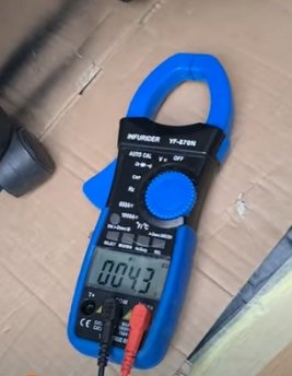
BTW what was the resistance reading on your meter when the switch was made?
BTW what was the resistance reading on your meter when the switch was made?
m80
MB Enthusiast
- Joined
- Apr 26, 2015
- Messages
- 7,197
- Location
- Derbyshire, High Peak
- Car
- Viano ex long, 651 2014. S211 646 2009 (till the Gov't drones blow 'em off the road)
The above drawings have proved useful.
I know there are more than 1 type of locking mechanism. Later there is the addition of a micro switch to the child lock, ealier locks didn't have this.
When I strip the door skin off I'll follow the wiring to understand better, but the drawing aren't totally correct to my set up, but for for the lock 2nd stage micro switch it looks to be.
So I've tested n/s and o/s to compare.
As my n/s works as it should that's the base line, so a difference on the o/s would hi lite my issue. This assumes that the fault is within the door.
On the n/s we can count from the top, on the top pins,
as 1 down to 5, and the same for the lower pins 1 at the top 5 at the bottom.
On the o/s, where my problem is, all is turned upside down.
Top pins become bottom pins, and the count is 1 at the bottom to 5 at the top.
Anyways, the suggestion to short from pin 1 to anything will short the solenoid, the SAM wouldn't like it, but it would, at least, disable the solenoid.
The switch, I think we are concerned with, is the lock switch. This, as said, closes at lock 2nd stage. I see this being across pins 2 and 5 (top pins n/s, lower pins (and upside down) on the o/s).
I have recorded varying resistance across those pins when the lock is manipulated closed.
When the resistance is low the system works ok.
Above somewhere around 5 ohms the rear doors fail to lock. I've measured as high as 30+ ohms.
Clearly the door is still open when testing, and I don't know the actual resistance when I do actually attempt to close the door, that's assumed to still be high after measuring a high resistance.
So I frigged a short, within the door, across 2 and 5. The door stops moving just prior to 2nd stage. It closes, latches on 1st stage, and stops.
I assume the system sees the closed lock and cuts out.
In fact if you forget to release the manipulated closed lock and close the door the system does similar, but before the 1st latch.
My conclusion is that the lock micro switch is the culprit.
I'l do some more testing to be sure it isn't one of the connections. I did this at the plug behind the pins and it isn't there.
Somewhere close to £250 for a new lock feels painful.
A local chap believes he can do this repair for £65, so I'll give him the chance.
Afternoon all....
So been playing this morning / afternoon and its packed up again ...AHHHH.....
But in a good way because Now I can use my Fault finding skills and start tracing wires ... Contacts etc
WELL... well the trusty contacts on 2 & 5 are definitely intermittent as in they work... dont work and after reading about one of you guys and a switch on the pins .. ohh hang on all we need is something to make a CLOSED circuit and then I went into simple mode so forget about relays etc we need a simple open closed gizmo.... so into my work shop looking for some bits ...
all we need to do is find a place on the Pillar and door to best place things .. I want the Magnet on the door high or low so not to get knocked off the REED switch will be glued fixed to the passenger door pillar or the plastic where the Seat belt goes behind ... so people thoughts on where to place contacts out the way ... well just watch this video ... SIDE DOOR CLOSE EASY FIX
Gazza
m80
MB Enthusiast
- Joined
- Apr 26, 2015
- Messages
- 7,197
- Location
- Derbyshire, High Peak
- Car
- Viano ex long, 651 2014. S211 646 2009 (till the Gov't drones blow 'em off the road)
I foresee 2 issues using a magnetic reed switch.
Reed switch on one metal plate,
magnet behind or on another.
Will the reed switch sense the magnet?
As I found just by shorting 2 & 5, there is a precise action recognised by the system.
The set up needs to discern between 1st stage lock and 2nd stage.
On seeing the closed loop on 2 & 5 the motor stops, well it did with my frig. I'm assuming that is because the pins have made contact with the pads.
'If' the reed can sense the magnet, the distance between the 2 would need to be precisely set, so adjusting one component becomes necessary.
I considered installing a plunge switch. But the problem of precise adjustment is still true. Easier though.
Yea just playing around at the moment but... IT WORKS that's the best bit.
I'm just playing & looking at the moment I've just tried a few positions but I'm not happy with the lay out.
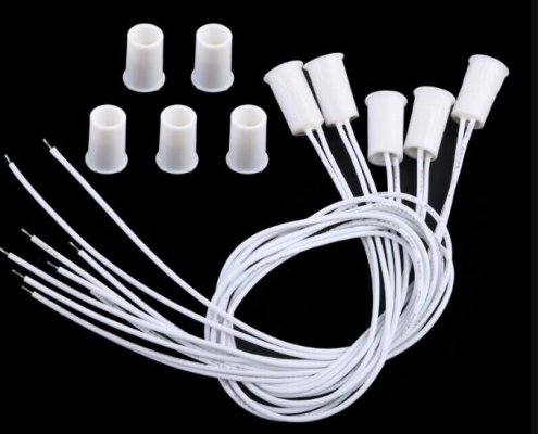
So was thinking more of CONCEALED types so I've just ordered 5 of ebay to play with drill a 10mm hole and sikaflex in place the Magnet i'll 3D print a threaded post so to adjust it but again all R&D at the moment but as can be seen from the video ..IT WORKS ... LOL
Attachments
V6nut
New Member
Good idea but I think it might depend if you have the later or earlier type of lock as mentioned by m80. I think mine is earlier type (2008) as the short across 2 and 5 doesn’t give me the issue that m80 describes. If you have the later type I agree with m80 in that I think the adjustment of a magnetic or plunge switch will be very tricky.
Based on what’s been discovered so far I’m thinking I might just try a manually operated switch on the dash that puts a short across 2 and 5. This can be wired into the contacts on the pillar side. When the switch is closed the rear should lock OK and the ‘door open’ message shouldn’t appear. With the switch open the door opening buttons on the dash and door pillar should work normally (they don’t when the short is across 2 & 5). I think this might work for both early and late types of lock.
Based on what’s been discovered so far I’m thinking I might just try a manually operated switch on the dash that puts a short across 2 and 5. This can be wired into the contacts on the pillar side. When the switch is closed the rear should lock OK and the ‘door open’ message shouldn’t appear. With the switch open the door opening buttons on the dash and door pillar should work normally (they don’t when the short is across 2 & 5). I think this might work for both early and late types of lock.
@V6nut No your correct its pins 2 & 5 on passenger from the top and the same on Drivers BUT its numbered from the bottom going up so drivers door is
BOTTOM PINS are
10
9
8
7
6
{*}
5<<<
4
3
2<<<
1
and on Passenger side there TOP PINS
1
2<<<
3
4
5<<<
{*}
6
7
8
9
10
just place a bit of insulation tape on the pillar contacts (one @ a time ) to block the pins from touching and start jotting down the things it dont do ?
You be surprised @ what works & what dont but keep watching the dash close door BUTTON for flashing faults on the LED some stay on some are on thern 4 seconds later there off ... I need to right all these down so I know what all the faults are ... LOL
Last edited:
m80
MB Enthusiast
- Joined
- Apr 26, 2015
- Messages
- 7,197
- Location
- Derbyshire, High Peak
- Car
- Viano ex long, 651 2014. S211 646 2009 (till the Gov't drones blow 'em off the road)
Mines looking good so far.
New switch on the locking mechanism, and the van is happy to lock and alarm.
For me the best part is being able to leave the rear area with lights not disabled.
Anyways, the door card can stay off for a week or so till I'm confident all is good.
New switch on the locking mechanism, and the van is happy to lock and alarm.
For me the best part is being able to leave the rear area with lights not disabled.
Anyways, the door card can stay off for a week or so till I'm confident all is good.
V6nut
New Member
You’ve replaced the microswitch?Mines looking good so far.
New switch on the locking mechanism, and the van is happy to lock and alarm.
For me the best part is being able to leave the rear area with lights not disabled.
Anyways, the door card can stay off for a week or so till I'm confident all is good.
m80
MB Enthusiast
- Joined
- Apr 26, 2015
- Messages
- 7,197
- Location
- Derbyshire, High Peak
- Car
- Viano ex long, 651 2014. S211 646 2009 (till the Gov't drones blow 'em off the road)
Local chap did. A retired friend of a friend.You’ve replaced the microswitch?
He has a stock of electronic bits and bats, so adapted one for the purpose.
Lock taken out this morning,
he rang this pm to say ready,
collected, fitted and tested a bit later.
It isn't the same as original, but looks fit for purpose. The soldering (of the 2 wires) is obvious. But it isn't going to be seen anyway.
But because I've been here before I'll run for a while before refitting the door card. I have curtains in mine so the removal / refitting is a tad more involved.
The difference this time is that I witnessed the higher resistance across 2 & 5 when closed, and that resistance varied. The post 16 drawings were handy for that, thanks Gazza.
Hey V6nut glad you got it sorted ..
Any chance of some photos with the door card off love to see what's involved etc I looked but was afraid to take it off ... So Just in case I may need it if this fails ...
But in the meantime I was playing around and started to get the hover out to clean the passenger side door footwell.
Loads of saw dust as i'm still in build mode ...
So with the footwell exposed.... oh my word found the sweet spot for the reed switch and magnet and i'm pleased to say it works a bloody treat so without further ado here's the finished video contacts and door lock and alarm is working fine must admit I was getting annoyed with my self as it worked fine and with 3 attempts would it lock would it hell as like ... only to find out I left the bloody tail gate open
 so here's the video and I just broke into the wires on the passenger pillar connected into pins 2 & 5 soldered and taped over DOOR MAGNET position
Any chance of some photos with the door card off love to see what's involved etc I looked but was afraid to take it off ... So Just in case I may need it if this fails ...
But in the meantime I was playing around and started to get the hover out to clean the passenger side door footwell.
Loads of saw dust as i'm still in build mode ...
So with the footwell exposed.... oh my word found the sweet spot for the reed switch and magnet and i'm pleased to say it works a bloody treat so without further ado here's the finished video contacts and door lock and alarm is working fine must admit I was getting annoyed with my self as it worked fine and with 3 attempts would it lock would it hell as like ... only to find out I left the bloody tail gate open
 so here's the video and I just broke into the wires on the passenger pillar connected into pins 2 & 5 soldered and taped over DOOR MAGNET position
m80
MB Enthusiast
- Joined
- Apr 26, 2015
- Messages
- 7,197
- Location
- Derbyshire, High Peak
- Car
- Viano ex long, 651 2014. S211 646 2009 (till the Gov't drones blow 'em off the road)
Unlikely that'll be today,Any chance of some photos with the door card off love to see what's involved etc I looked but was afraid to take it off
but sometime later.
V6nut
New Member
Well done Gary! That looks like a great solution and very neat once the trims are back on.Hey V6nut glad you got it sorted ..
Any chance of some photos with the door card off love to see what's involved etc I looked but was afraid to take it off ... So Just in case I may need it if this fails ...
But in the meantime I was playing around and started to get the hover out to clean the passenger side door footwell.
Loads of saw dust as i'm still in build mode ...
So with the footwell exposed.... oh my word found the sweet spot for the reed switch and magnet and i'm pleased to say it works a bloody treat so without further ado here's the finished video contacts and door lock and alarm is working fine must admit I was getting annoyed with my self as it worked fine and with 3 attempts would it lock would it hell as like ... only to find out I left the bloody tail gate openso here's the video and I just broke into the wires on the passenger pillar connected into pins 2 & 5 soldered and taped over DOOR MAGNET position
I noticed your aftermarket audio head unit, that looks like a good fit in the available space. What make/ model is it?
In addition I’m also in the midst of a camper conversion, what curtains have you gone for? They look pretty nice.
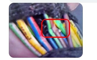
V6nut here you go also the trapped and damaged wires under the passenger footwell this caused no end of faults with the srs restraint message on the dash but here is the video of a small tweak on the double bounce on the door if you get it ... Side door TWEAK if needed Curtains ... radio ...etc
Attachments
Last edited:
Users who are viewing this thread
Total: 2 (members: 0, guests: 2)
Similar threads
- Replies
- 3
- Views
- 314
- Replies
- 1
- Views
- 347
- Replies
- 8
- Views
- 475
- Replies
- 2
- Views
- 244

