• The Forums are now open to new registrations, adverts are also being de-tuned.

Viano / Vito 2012 W639 Electric Sliding Door Lock Issue. Possible Solution

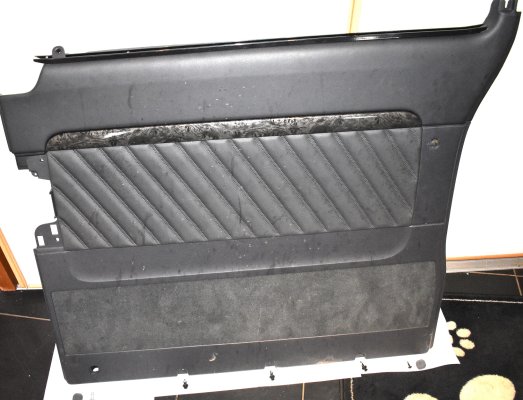
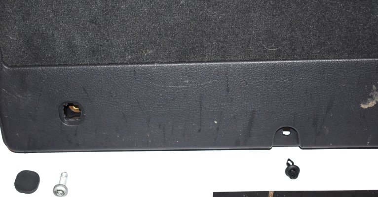
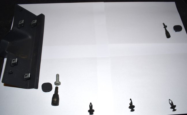
The larger screw, lower forward, is a T45.
The smaller screw, higher rearward, is a T25.
Both behind push in covers.

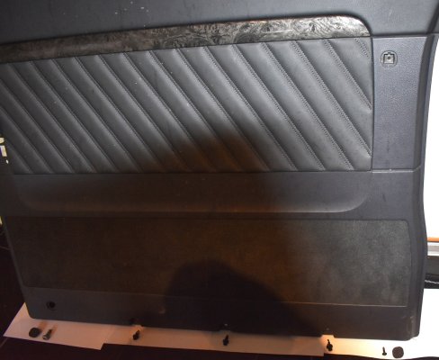
Along the bottom are 3x pushins, with cross head plastic screws into those.

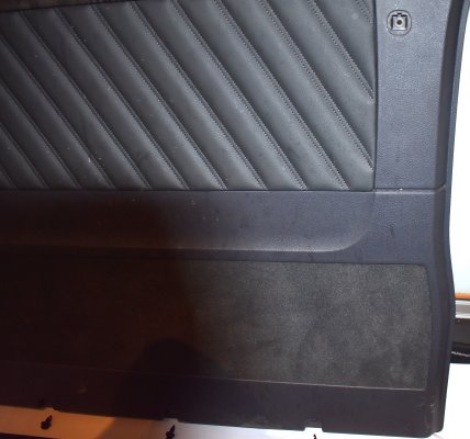
The lock button trim needs to be prised upward and removed prior to card removal.

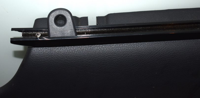
The plastic bulge cover, over the heavy door stop, is just prised clear. Removal of the door stop is easy, but perhaps not required.

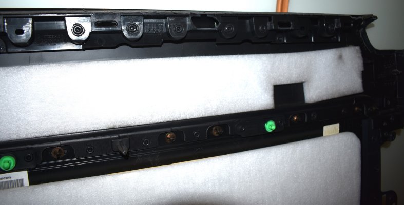
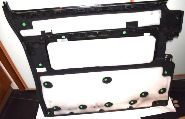
On the blind side, at the top, can be seen the plastic that pushes onto steel clips on the door. If cold this can be brittle. The photo shows one part of the plastic has broken off.
 

Attachments

  • a-Offside sliding door card.JPG
    a-Offside sliding door card.JPG
    1.1 MB · Views: 13
  • g-Top 'brittle' plastic.JPG
    g-Top 'brittle' plastic.JPG
    650.5 KB · Views: 14
  • f-Door card blind side.JPG
    f-Door card blind side.JPG
    536 KB · Views: 15
  • e-Lower rearward.JPG
    e-Lower rearward.JPG
    869.3 KB · Views: 13
  • d-Lower forward.JPG
    d-Lower forward.JPG
    995.8 KB · Views: 13
  • c-Lock button trim.JPG
    c-Lock button trim.JPG
    569.5 KB · Views: 12
  • ac-Fixings.JPG
    ac-Fixings.JPG
    319.2 KB · Views: 13
  • ab-.JPG
    ab-.JPG
    353 KB · Views: 13
Blimey m80 it looks a right pain of a job and where's the lock ? is that the same to get too ... bloody hard i bet
 
The lock is at the back of the door, opposite the hasp on the pillar.
Accessible from the inside, held by 3 torx screws.
Release those and the lock needs to be manipulated forwards before it can be swung inwards on the 3 wire rope cables.
Some twisting, up / down manipulation is needed to free it. And watch for sharp edges on the fingers.

When freed the wire rope cables need be prised out of the mechanism, the ends lifted / rotated free, and then unplug the electrics. On mine there are 2 plugs, on earlier just one.

Mine's back together now.
I'm waiting for a new middle rear roller, as the bearing has collapsed on one of 'em, possibly due to my slamming it when it didn't want to lock.

There are 2 types of those also. For the electric doors there are 2 lugs underside, for the pull / push rope cables to clip onto.
Then I'll run the normalisation programme again, even though it is doing as it should. And I reckon, like lecky windows after a battery change, up down, and hold the button up for a few seconds should do it anyway.

Oh, if anyone is changing their rear roller, watch out as when un bolted the door will want to fall rearwards. That's all that carries the back of the door.
 
It's within DAB (Star).
But I would have thought that opening / closing a few times would do it.

After replacing a battery often a window will drop an inch after closing. If the window is opened / closed a couple of times and the open button held up a few seconds that overcomes the dropping an inch.
'Course with the doors there is no obvious 'up' button. But maybe the dash button, or pillar button, would do instead?
 
This post has been a life saver, particularly the one with the micro-switch removed. I zoomed, cropped, cleared the background, and reverse google searched the image. I located a G303-130E05A3-FA P67 wire type waterproof micro switch for car door lock on AliExpress. This is not an exact match, but is close enough to do the job. And so, for a couple of quid, your van door issue will likely be gone.

The switch varies on having three wires (I cut the middle one out, as the grey and black are the ones you want (which coincidentally are the same as those in the lock). The locating pins unfortunately are only on one side, and they are approximately twice as long. So you'll need to cut them down, or you'll have trouble inserting them. The RHS lock is very straight forward, but I recommend adding some kind of mastic, glue, to the left to ensure it doesn't move, do to the lack of locating pins. And the activation tang needs to be cut back just before the bend, so that it is only as wide as the switch in the depressed position.

I really regret not taking pictures of my own, and I'm not about to take it apart to show you now. However, I'll describe the process, and if you have questions I'll try to answer as best I can

1. Remove door skin. There are 4 screws in the door, two beneath small square covers that can be popped out. These are star (no idea what they are officially called) slotted screws. The other two are located under the cover of the door opening stop. There are 3 expanding plug fasteners along the bottom (good luck getting these rotten things out in one piece). After removal of the screws and the plug fasteners, gently pries the panel away. All fasteners push into the door, so simply pull it out away from the door.

2. Unscrew the lock from the door, this is obviously done from outside of the vehicle, with door open.

3. Remove the lock from the car by unplugging the two electrical connectors, which have clips that you squeeze together before pulling apart.

4. Remove the actuating wires. Place a flat bladed screwdriver under the plastic at the point the wires connect to the lock. Gently pries up, and they will pop out. Lift the black wire, rotate 90 degrees and remove from the lock. Repeat with the longer of the two white wires. The last of the wires just needs to be lifter 90 to extract from the mechanism.

5. Remove the electron actuator and the plastic shield. There are 3 screws securing these items. find the two wires (one grey one black) going from the actuator to the micro-switch. Cut these halfway. (This stops the actuator from flying around whilst you extract the switch.

6. Using a flat blade again pry the black plastic casting that holds the switch in place. Slide it out in the along the line of the two locating pins. This is tricky, feel free to swear a lot at this point. (take note of the orientation)

7. Insert the new switch, remembering that the open end of the switch lever goes into the lock first. The right hand side will click into place, but the other may not, depending on the condition of the end of the plastic plat where you extracted the old one. For the left hand side, try adding glue or some form of adhesive to ensure the switch doesn't move. Solder the wires to the actuator and reverse the instructions to put everything back to get.

8. Smugly open and close your doors free of error lights.
 
Brilliant! Please could you attach a link to the switch you bought, or is it simple a case of searching on the code you have kindly listed? Sounds like an ideal fix.
Well done!
 
Whilst I'm done with this, I did find a manufacturer on AliExpress who may be able to provide an exact copy. There is even a breakdown of the codes to "describe" the switch required.

I reckon something like G303-130E02B12 would be about right.
Brilliant! Please could you attach a link to the switch you bought, or is it simple a case of searching on the code you have kindly listed? Sounds like an ideal fix.
Well done!
It's at the top of the post, but searching should work too. 2.61ï¿¡ |G303-130e05a3-fa P67 Wire Type Waterproof Micro Switch For Car Door Lock - Switches & Relays - AliExpress

It's in Aus pesos, so really only a couple of quid for you wealthy English types.
 
New micro switch fitted into the lock on mine on 4th March, so far so good.
Tbh, apart from lock replacement, it seems the easier way to go with these.
 
Wow, I never knew my simple post would generate this long a post. Loads of useful info on here. I'm back because my micro switch bodge, Has deteriorated over time ( knew it would ) to the point that now if you stop at a junction the doors open by them selves. Which adds to the fun. It did solve the issue for quite a long while though, so proved to myself that the micro switches are the cause of all the issues. Resigned myself to buying new actuators. but bulked at the price and the unavailability. Loving the Magnetic reed switch solution. That seems like a hundred year fix. But to keep it all original, I will get a couple of micro switches. via Ali express. and wire them in. Thank you all for your help.
 
So I tried the possible solution that m80 came up (but subsequently rejected as it was thought it would cause other issues) in order to see what the downside would be. I snipped the wires coming from pads 3 & 4 on the door pillar, then I connected together the stubs coming from the pads. Next I spliced together the wires coming from the door pins that contact the pads when the door closes ( just stripped the insulation a little without cutting the wires) I connected 2 to 3 and 4 to 5. This then gives a connection from 2 to 5 when the door is closed.
This fixed the issue with the rear central locking, pressing the key locks all the doors. I no longer get the ‘door open’ alert when driving either ; so two very annoying issues resolved!
Unfortunately the side effect of this ‘fix’ is that the door will not open when either the dashboard switch or the B pillar switch is pressed. Pressing the unlock button on the door or the outer door handle works fine. So the only downside really is that you can’t open the door from the drivers seat - something I never, or very rarely do anyway - so I’m very happy with this fix and definitely won’t be forking out £265 for a replacement door mechanism.
This fix worked for me on 2007 model, no electric doors so nothing lost. I was working on UK driver side so pins were 1-5 from bottom. Thanks for all the help. I’m happy I didn’t need a new door lock which in Ireland was going to cost 460€ ex vat !!!
 
Is voltage a cause of this?

Ok, so sensors have arrived. However our van is an intermittent use vehicle. It will sit for a couple of weeks and then get a flurry of use and then back to sitting on the drive again.
Now the battery has always been lazy, it always starts the van but struggles. If I leave it for weeks I sometimes have to pop a jump start on it. I always meant to change it, just didnt want to pay out for the battery.
However, the doors had reached a point where they had been an absolute pain. Constant hassle, but the van has done some really long drives over the last couple of weeks. At least 5 hours each trip. And low and behold, now not a blip from the doors, nothing. Van starts on the button.
Could it be that the threshold voltage between a digital low and digital high was close enough with the old battery to cause these issues, especially with a slightly high resistance sensor? I know the alternator should keep the voltage at a set value once its running. But struggling to understand how a fault that was so bad has now completely vanished?
 
Just a follow up on this thread. My daughter has a 2012 Viano with both rear doors playing up intermittently with all the symptoms mentioned... Passenger compartment not locking, door open indicator coming on while driving, doors actually opened a few times while driving, alarm goes off sometimes if they did lock (occurred when the sun came on the door), and the most annoying the battery going flat. (found it was the footwell lights staying on at 10 watts each due to door lock indicating it was still open but no switch lights on the dash indicating this).
The intermittent nature of the symptoms indicated it was a micro switch fault so eventually I took out the door locks and tested the switches just with an ohmmeter and both had a minimum resistance of over 10Kohm so I was surprised the doors ever locked so the door control unit must be very tolerant of required voltage drop to see they are closed.
Having removed the switches as previous contributors have explained I tried dozens of presses of the switch with no improvement and tried putting some load through it to operate a 2 watt bulb, this finished off one switch completely and the other went over 1Mohm so now I had no option but to source new ones.

The switches are made by Cherry, the same company that make keyboards, and their catalog show them but I could not find any so ordered some similar items from Ali express, link below.
These have exposed terminals and you use the two outside ones and I cut off the middle one, soldered and insulated short wires to the others. The lever from the old switch is easily prised out of the plastic case and pushes straight into the new one.
The main issue is as mentioned on a previous reply the replacement switches only have locating lugs on one side whereas the original had lugs on both. The pictures of the new ones was not clear and there are two options which I did not spot until they arrived so my advice is order one type a and one type b, for both rear doors @£1.50 each, this will save the fuss I had making some lugs and securing to the switch.

The switch just pushes into the lock assembly with a bit of care and the lugs are most secure when slotted into the oval hole on the outer side. I did use a very small amount of adhesive after to help ensure it does not move.
After testing several times the switch read less than 1 ohm when operated and with the locks refitted all has worked fine for a few months now and my daughter is off my back.

I have since found other switches on ebay that would have done the job, search for sub miniature door switch, it seems they are popular for the V W range.
I know a lot has been previously covered on this subject but just thought my experiences might help.
Here is the link for the ones I purchased.

Attached picture shows switch inserted bottom right with lugs showing in oval20241203_182619361.JPG
 

Try these,
I think I used 2x 2.5mm (diameter) self tappers to secure.
There may be a need to bend the spring actuator a tad for correct operation,
using a dvm while on the bench.
 
Same problem with my 2004 vito, fob only locks and unlocks the front doors, tailgate only unlocks remotely. Door open signal beeping when driving.
Thanks for all the info in this thread, I have all the door cards off and access to all the locks and wiring.
As I don't have electric sliding doors like yours, it should be simpler? if I permanently connect 2 and 5 behind the pins of the sliding doors, the car will think these doors are closed. I don't have to worry about an electric door closing mechanism as I have to open the doors manually.
so I did this and testing the resistance at the pins I have continuity between 2 and 5 (logically) (also 2 and 4, and 1 and 2., as well as 1 and 5 and 1 and 4 on both sliding doors).
I shut the doors and drove and the door open beeped just as before, s***!.
So, back to the tailgate lock which I had dismantled to test the little motor and its micro-switch. I found the second micro-switch inside the sealed lock bit and it works fine. No resistance when the door is shut, that is, closed circuit between 2 and 4 (blue/black and blue/green). As well as 1 and 2, and 1 and 4
Tested the car and still beep beep.
I looked at the wiring diagram and wondered if 3 should be connected as well, so wired it to 4 for good measure.
No difference, still beep beep grrrrr.
Back to square one.
Do I have to check the wiring in the door frame?? Should I have connected 2 to 3 and 4 to 5 behind the door pins and put a switch between 3 and 4 on the pillar side as was suggested above??
Maybe my problem is between the door frames and the van's computer. How do I test that??
 
Maybe my problem is between the door frames and the van's computer. How do I test that??
W/o a wiring diagram I couldn't analyse the testing / frigs you have done.
But this will all go to the SAM.

That is the unit mounted underside of the fuse / relay tray.
There are several plugs that connect into that on the underside, my guess is that one of those plugs will be the appropriate connection to the SAM. I couldn't tell you which, w/o referring to Star anyway.

It's a v busy area around the SAM, but you may be lucky in identifying a problem there.
When a SAM goes faulty it often confuses many functions. But I do have a SAM that I keep for diagnostics, that only has arear interior light issue. So while not common to only have one issue it is possible. Especially if you have inadvertently sent the 12 volts the wrong way???
 
I don't appear to have any other issues with the van apart from a leaking injector but this is not relevant here!
I have been studying the wiring diagram of the central locking till I'm blue in the face, not being a mechanic, just a diyer.
As I thought my problem was the red and blue and red and black wires, I found what I think is 8 (2 and 1) in the sam see photo (not mine, taken from internet). I may be very wrong. The sam connector 3 which has more than 20 connectors includes the 3 other tailgate and the R sliding door wires but I haven't located this.
Anyway, it would be beyond me to remove the fuse box and the various modules!! But if I could be sure, I'd take it to a mechanic.
I'd like to know where X43/10 connector is located
 

Attachments

  • vito lock wiring .jpg
    vito lock wiring .jpg
    246.9 KB · Views: 2
  • sam under fusebox?.jpg
    sam under fusebox?.jpg
    95.4 KB · Views: 2
Ime having the same problem, doors not working
 

Users who are viewing this thread

Back
Top Bottom