• The Forums are now open to new registrations, adverts are also being de-tuned.

280GE Gwagen.. owning an modifying my 30year old Mercedes.

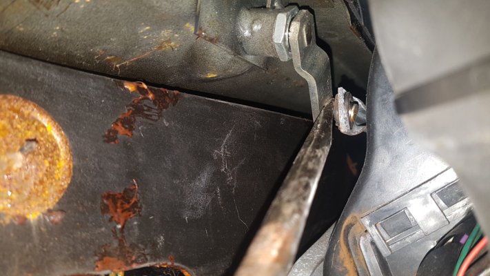
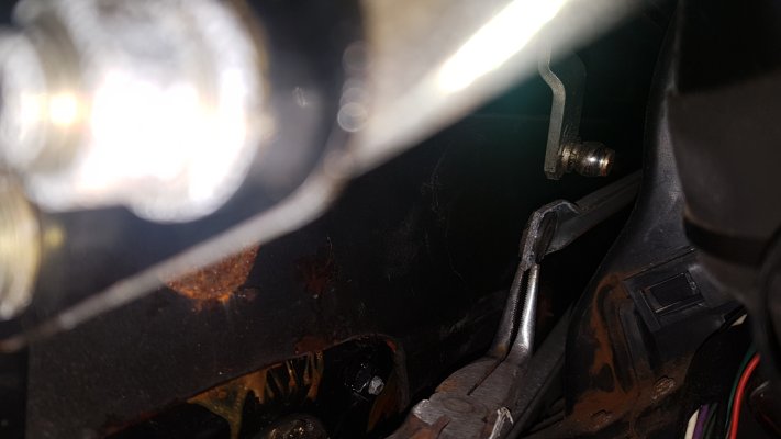
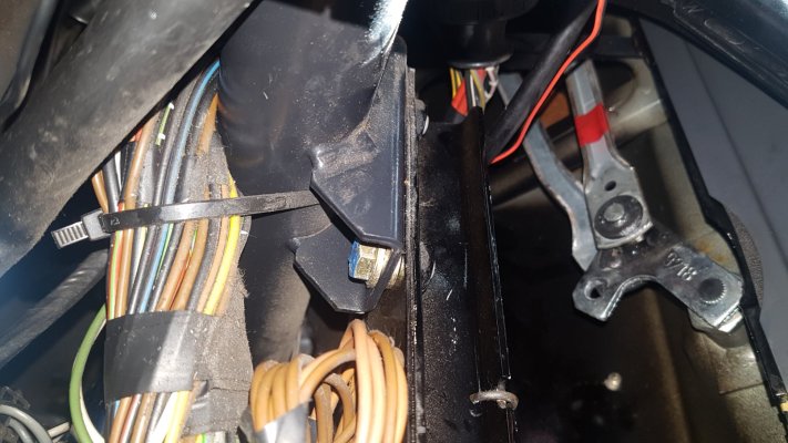
20200505_133333.jpg
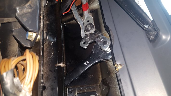
20200505_133519.jpg

You will see this linkage is straight, and has an open ball-joint head. make note of it for future reassembly identification

Step 10
Next we move over to the drivers side (RHD)
and if you look carefully through the opening on top of the dash you will see the drivers side wiper spindle linkage.
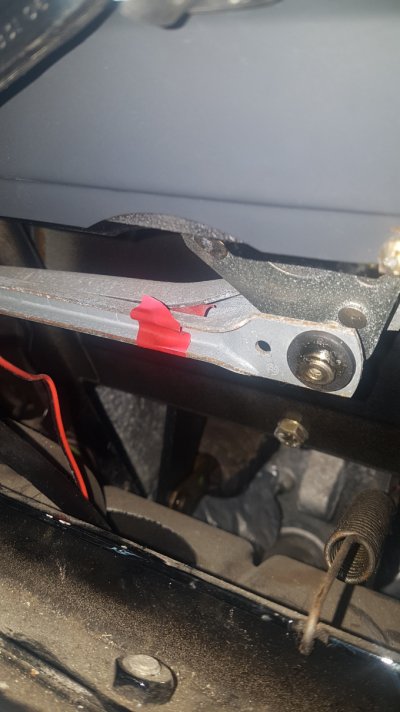
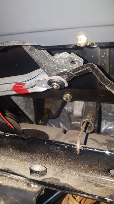
red tape.jpgdrivers wiper linkage.jpg
This linkage has two ball joints and connecting rods.
The wiper motor links to this to operate the drivers side wiper (Crooked linkage) and continues on through the second linkage to the passenger wiper (straight linkage)
For my reference i marked the front passenger side linkage with some red tape to assist in re-assembly and so i knew which end went where.
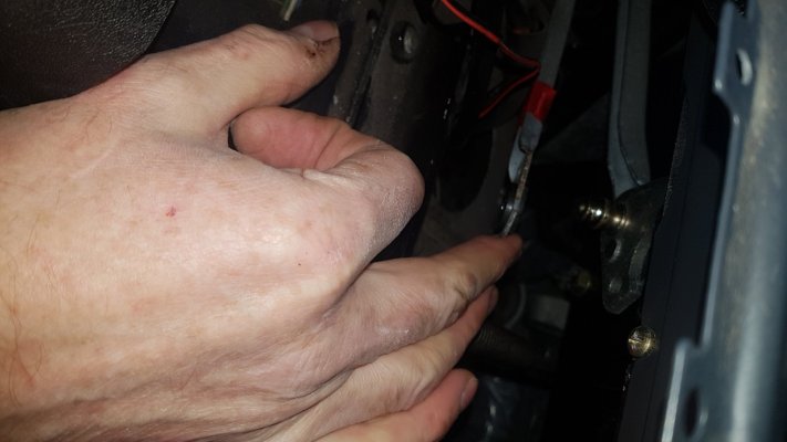

20200505_143117.jpg
Using the same method as before carefully pop off both the front and rear wiper linkage rods. You can leave them in place if you wish as there is no need to remove them.
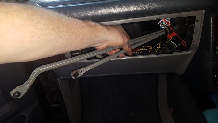
20200505_143503.jpg

If you buy a complete linkage from Mercedes, you will still need to dis-assemble it to be able to slide the linkage rods through the small space behind the heater.


Step 11

Now we finally come to the removal of the wiper spindles themselves.
for this you will need an assistant, x2 -22mm open ended spanners (or x1 -22mm open ended spanner and a large adjustable spanner).

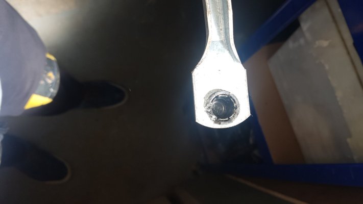
Lets begin with the passenger side (RHD) use the open ended 22mm spanner to hold the nut on the rear of the passenger side wiper spindle.
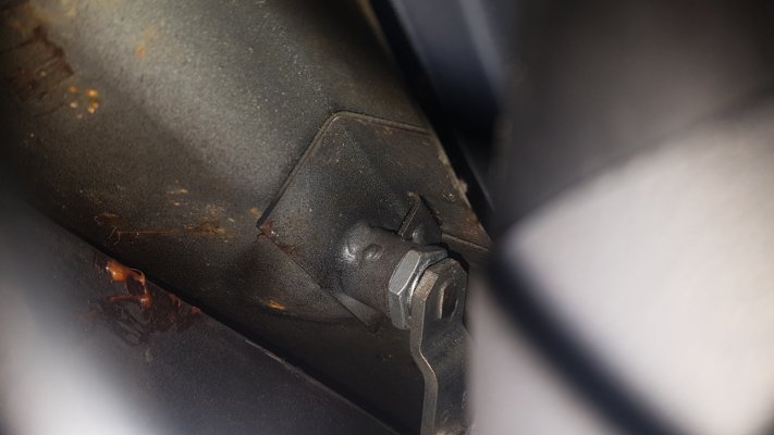
20200505_132725.jpg


Your assistant should now start to undo the nut on the outside of the spindle, having first protected the area with cloths or some masking tape to avoid paint damage...

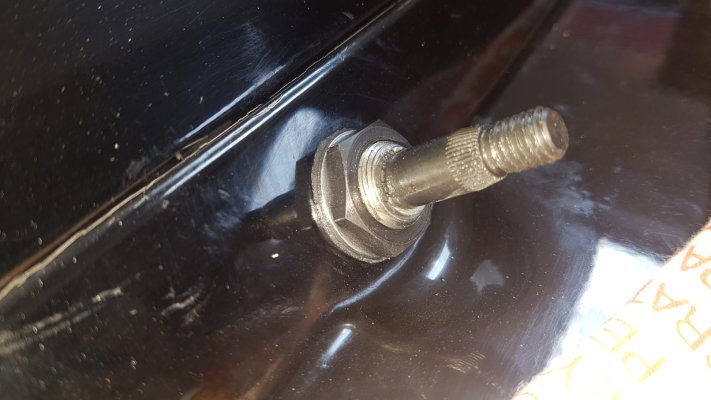
once undone, carefully remove the nut, metal washer and whats left of the old sealing washer.. the spindle should then come out from the hole under the dashboard.

Step 12
Lets now move onto the drivers side spindle... which you will see through the hole where the instruments once sat.

same procedure... 22mm spanner on the nut on the inside, and if like me you have long arms... you may be able to reach the nut on the outside and undo this one on your own, and remove it into the inside of the car..

Step 13

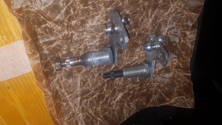
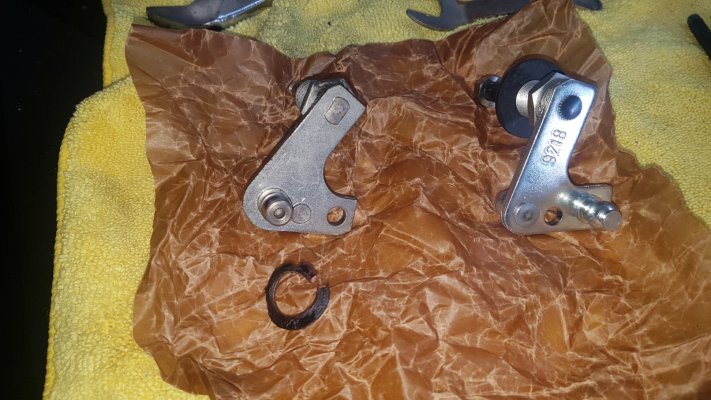
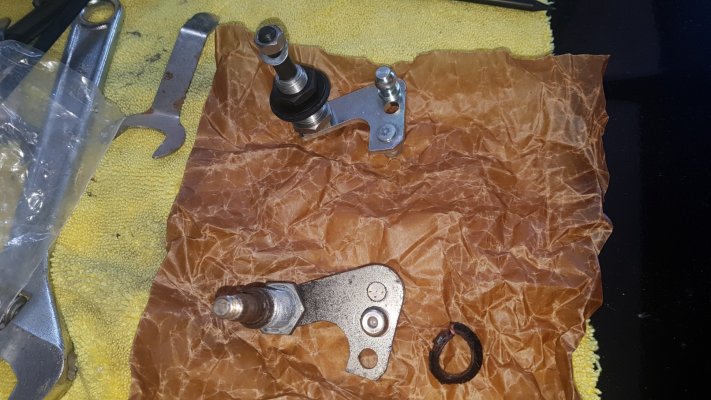
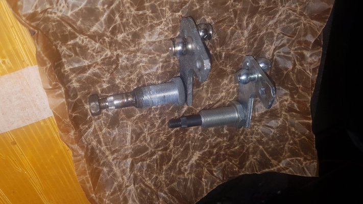
Now with both spindles removed lay them next to your new ones and look for any differences.
The passenger side may have a slightly cranked arm.. and the new one straight- this will make no difference once fitted.

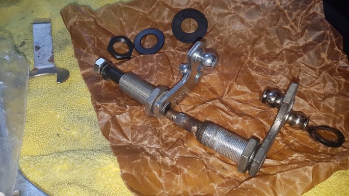
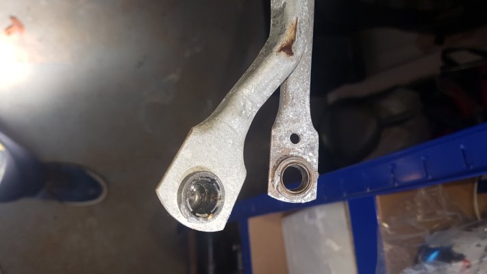
The drivers side wiper spindle must have all the ball joints on the new one in the same positions as the old one... If they are, no problem.
If you find (like me) the drivers side spindle has all the ball joints in the wrong place, they will need to be moved. For this you will need access to a mig welder or someone who can do it for you. (All the info on this is in its own section at the end of this thread).
Here are some examples;
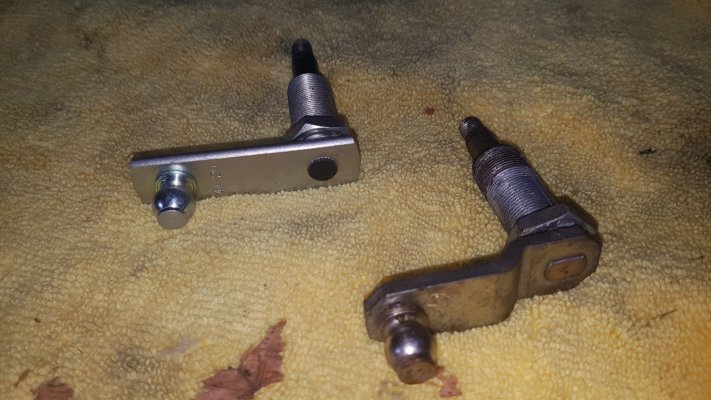
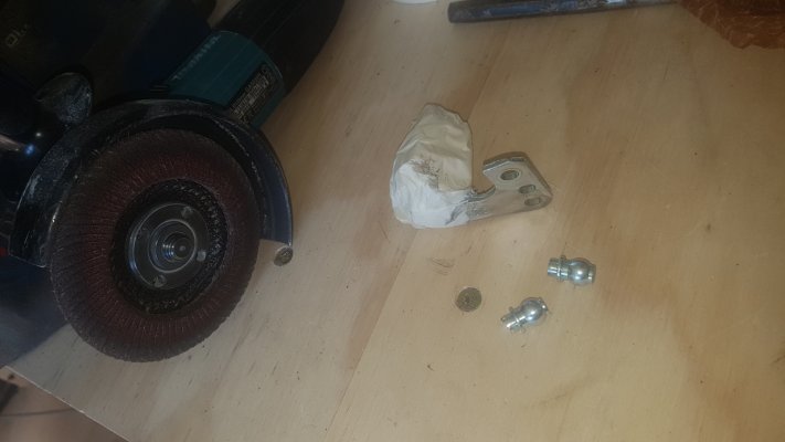
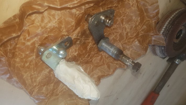
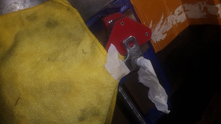
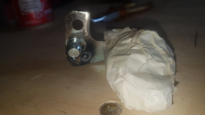
20200505_141931.jpg20200505_144557.jpg20200505_144515.jpg20200506_110057.jpg
last pic. New Wiper spindle for drivers side with ball joint positions corrected (by Me)

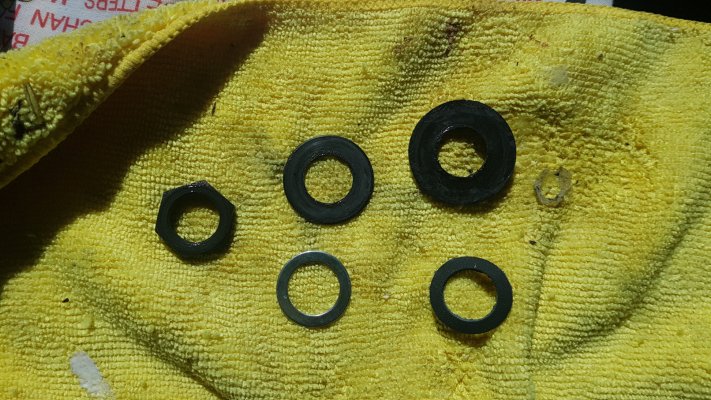
Check also that you have the correct washers, two shiny metal and two special cloth/rubber material washers.
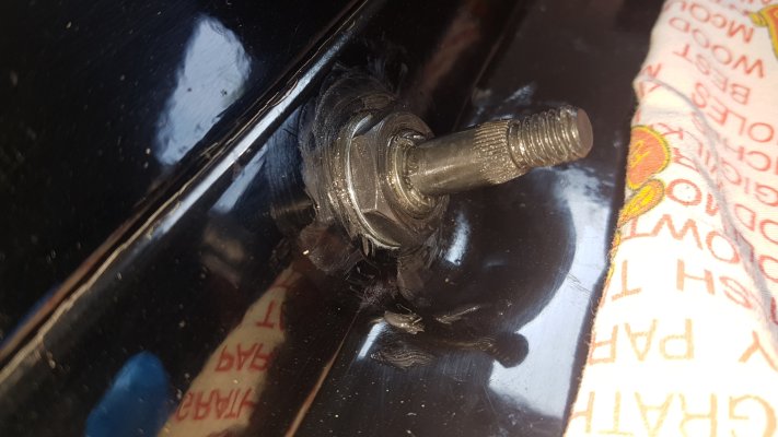
If you have a large black rubber washer and a black metal washer this is wrong. Do not fit these as the rubber washer is incorrect and will squeeze out under tightening of the wiper spindle and will not provide a water resistant seal. (I have no idea how I ended up with these, but had to obtain the correct washers from a friend) you should also have new black fixing nuts.. but if not you could re-use your old ones.
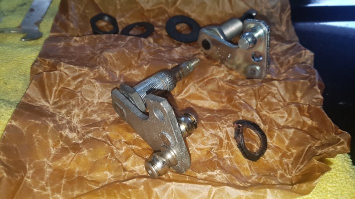
Here is a picture of the correct washers (bottom row), metal washer then special sealing washer.
Top 2 washers in this pic are the wrong rubber type washers .
20200507_111734.jpg


Step 14
Reassembly
.
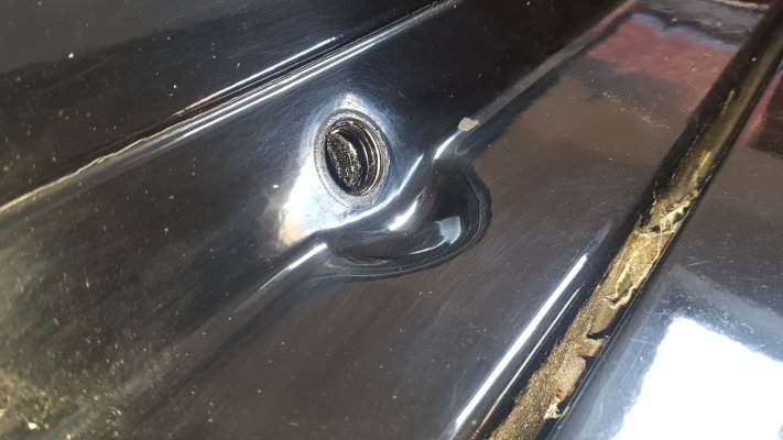
Assuming you have all the correct parts.. give the spindle holes some attention... clean them up, and if like mine they are chipped, touch in any paint chips and leave to dry (overnight is best) before-
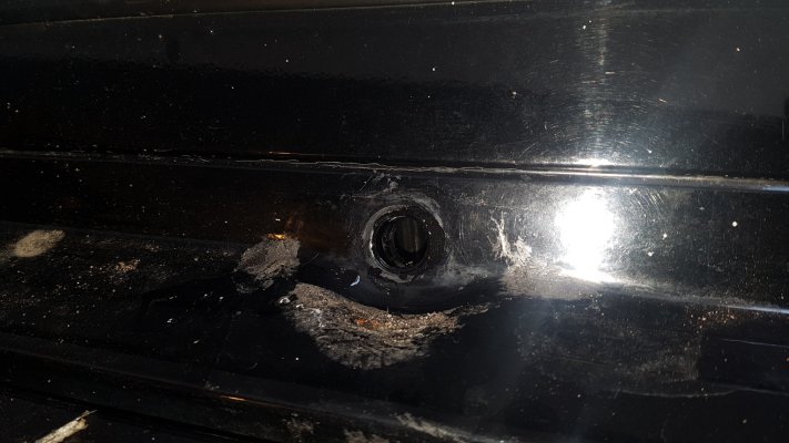
20200505_150424.jpg

After
20200506_110949.jpg
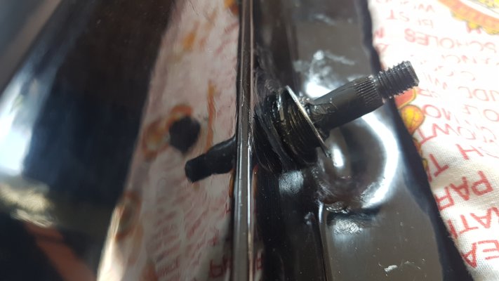
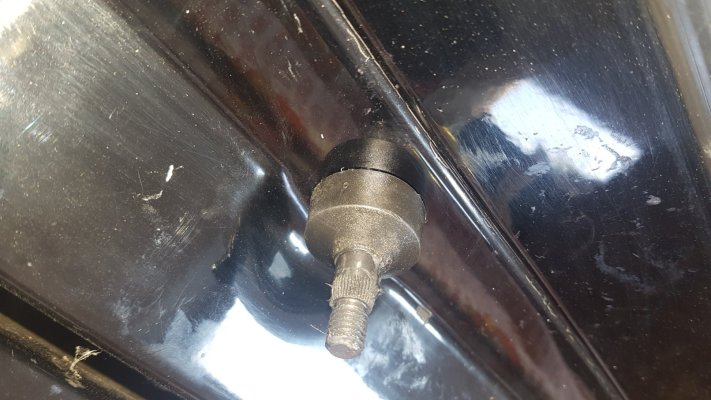
Once your Spindle holes are ready smear grease over the spindle and in and around the hole and insert the passenger side spindle from inside and smear some grease where the special cloth/rubber washer will sit, and slide it onto the spindle, next smear some more grease on the fitted washer and slide the metal washer on top. Now fit the black 22mm nut to secure the spindle, and with the 22mm spanner get your assistant to hold the inner spindle nut, while you tighten the nut on the outside of the spindle till its nice and tight. clean off the access grease and coat the inside of the plastic cup that covers the cap and slide it on.
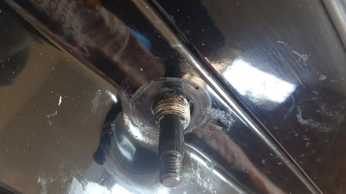
20200507_111754.jpg20200507_111914.jpg20200507_111943.jpg20200507_112212.jpg20200507_112241.jpg

The procedure for the Drivers side spindle is slightly different.
First you will need to make sure the the connecting rods are in the correct position.. if like me you removed them, you will need to temporarily tape them together so you can slide them in behind the heater in one go first threading them through the glovebox opening.. Once in there make sure the straight link rod is nearest you with the open side of its half round profile towards you.
The other linkage is cranked and this faces the same way as the front but attaches to the rear of your drivers side spindle, and has a closed ball-joint, which if it was fitted after poking the spindle through the hole in the bulkhead it would be very difficult to fit. If you can see the open profile of the linkage it is the correct way round.
20200505_145920.jpg
Grease the two ball joints on the link rods at the drivers end and both the ball joints on the drivers spindle. now carefully using a large pair of grips squeeze the ball-joint back onto the rear ball that faces the bulkhead.

Top
 
20200505_145929.jpg
20200506_122644.jpg
this is a bit awkward but take your time... and once you have the two ball joints pressed on manoeuvre the spindle through the bulkhead and attach washers and nut as and gently tighten.
To tighten properly you will need to rotate and slide the linkage to the passenger side, to gain access to the nut inside.

20200506_122731.jpg

then with your assistant tighten nut as before.


Step 15

Next we will be refitting the passenger side linkage arms to the new spindle.

This is slightly easier than the drivers side.
grease the ball joints on both the linkage arms and the ball they will connect to.
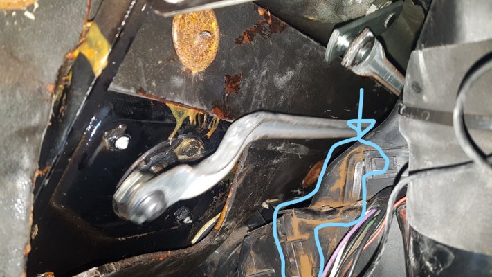
Squeeze with a pair of long nosed pliers or grips the straight link rod onto the passenger spindle ball joint. (top of picture)
and checking that there is no fouling, squeeze the cranked link rod onto the motor arm ball joint (Blue Nut)

20200506_120807.jpg
While you are there, check everything is fitted securely and turn on the ignition, and operate the wipers... there should be no grinding or strange noises, and allow the motor to park when you turn the wiper switch off BEFORE the ignition is switched off. your wiper arms are still not fitted at this stage.

Step 16

Once you have tested your spindles installation...
You can re-fit the wiper arms, using the sprung washers and new nuts.. Getting them in the right place can be tricky.
Test them with a wet windscreen, I sprayed mine with water so they were lubricated enough to park properly when they stop, (don't do it with a bone dry windscreen).

Step 17
Its now time to re-attach the bendy air vent pipes you removed for access to each side vent in the dashboard.
Re fit the instrument panel and don't forget to re-attach the speedo drive cable.
Re-fit the lower dash panels and glove box.
Fit the steering wheel
Re-fit the drivers seat

That should be the job of replacing your worn wiper spindles now finished.

This guide has been compiled from my own experience of changing my wiper spindles, with the guidance of others and as such should be viewed simply as such and in no way as a definitive method of changing W460 wiper spindles.
You will need a modicum of mechanical experience, some patience and dexterity, and some basic tools.

The author (me) does not accept any responsibility if you damage your G or sustain injury to yourself while following this Guide.
 
To view this content we will need your consent to set third party cookies.
For more detailed information, see our cookies page.


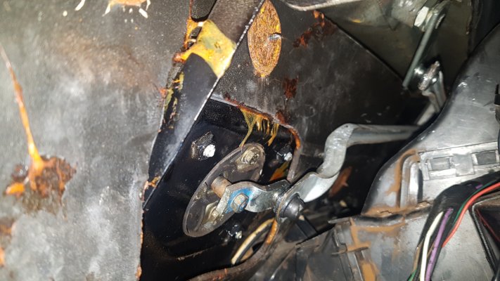
Rusty trail   circled.jpg

You can see the trail left by rusty water leaking into the cabin from the wiper spindle above.
Circled in blue
 
Re-Positioning the Drivers side wiper spindle ball joints if they have been supplied in the incorrect position.

Mine were! (and they are difficult to get hold of!)

Before you begin compare your old drivers side wiper spindle with the new one and if the ball joints are in the wrong place you will need to follow this extra Guide.

First you will need the following tools;
1.Angle Grinder with a abrasive wheel
2.A vice to hold the spindle
3. A hammer
4. A Heavy duty flat ended drift
5. Masking tape
6. MIG Welder (Or a person who can for you)

This was my old and new spindles compared note the ball joints in the wrong place

20200505_144415.jpg20200505_144428.jpg

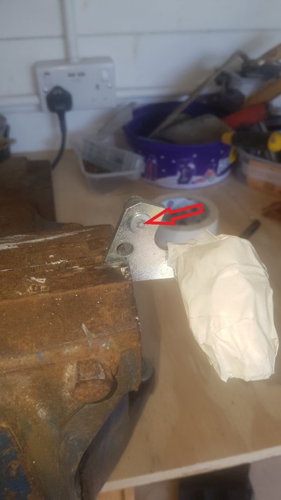
Wiper spindle pin.jpg


First you need to mask up the actual threaded spindle to avoid getting grit and dust into it, then clamp it in your vice.

Wiper spindle pin.
Using the abrasive wheel in an angle grinder grind off the small mound of the ball joint protruding from the opposite side of the bracket (Red Arrow) until it is level and flat with the bracket.

Then position the bracket so its supported both sides, and the ball joint is between the vice teeth but loose.
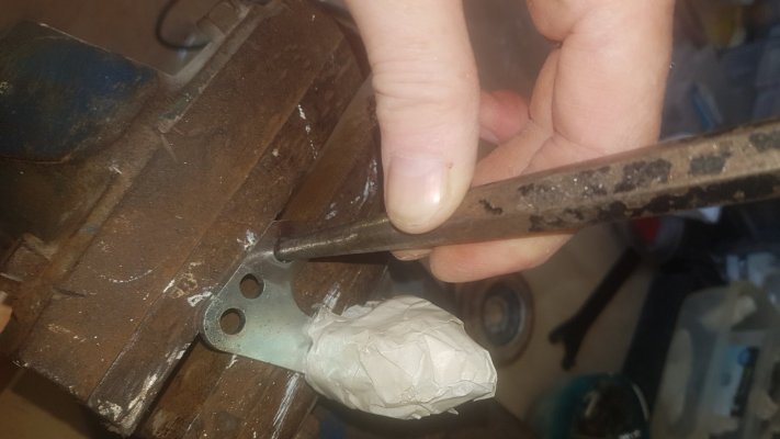
Drive out the ball joint from its opposite side using a drift and hammer.
20200506_102519.jpg

Complete this method for however many ball joints need moving


pins out.jpg
Compare the old spindle bracket, and tap the ball joints into the new hole positions.


pins relocated.jpg
The pins will now need to be MIG welded in place, from the rear and the welds cleaned up.20200506_103506.jpg20200506_104506.jpg

Make sure you cover the ball joints and spindle, you dont want any weld splatter on there.
20200506_110057 (1).jpg
Balljoint pins relocated.
 
Wiper spindle part numbers. (from a mate at MB)

W460 LHD Early up to serial 058985
A0008204346 left NLA
A0008204246 right NLA
Available – No – Note MB change both these to A463 820 22 46 But that it is just the seal kit!

W460 LHD Late from serial 058986
A0008207846 left NLA
A0008207946 right NLA
Available – No – Note MB change both these to A463 820 22 46 But that it is just the seal kit!

W460 RHD Early up to serial 058985
A0008204246 left NLA
A0008204346 right NLA
Available – No – Note MB change both these to A463 820 22 46 But that it is just the seal kit!

W460 RHD Late from serial 058986
A0008208046 left NLA
A0008208146 right NLA
Available – No - Complete Linkage Only


463 Series Wiper Spindles Only

W463 LHD
A0008207846 left NLA
A0008207946 right NLA
Available – No – Note MB change both these to A463 820 22 46 But that it is just the seal kit!

W463 RHD
A0008208146 left NLA
A0008208046 right NLA
Available – No - Complete Linkage Only


460 Complete Linkages

W460 LHD Early up to serial 058985
A0018207341

W460 LHD Late from serial 058986
A4638200041

W460 RHD Early up to serial 058985
A461 820 05 41

W460 RHD Late from serial 058986
A4618200841


463 Complete Linkages

W463 LHD
A4638200041

W463 RHD
A4618200841

Please enquire with chassis number for 463 after circa 2010 as the Wiper Systems changed several times from that point onwards.

Sundry 460/461/463 Wiper Items


Black Plastic Spindle Caps A000 824 35 72 (Same Front and Rear)

Wiper Spindle Seal Kit A463 820 22 46
(Included 3 sets of Spindle Nuts, Washers and Seals and also Wiper Motor Mountings)

Wiper Motor Mount Kit A463 820 18 41
(Just Wiper Motor Mountings)
 
A little saga with my 280GE last year which I thought I would share with you all, as I learned something new about my electrical system.

Whilst driving my G, I noticed something strange was happening to my rev counter.. It was going all over the place despite my revs being constant.. I thought how odd.. oh well I will have a look at it when I get home.
I stopped at where I was going and about half an hour later came out, ignition on.. Nothing except the warning lights... hmmm. My G has been behaving itself for a few years electrically so it was a mystery. Luckily a helpful fellow there allowed me to use his Jump start pack. Typical of me to have left mine at home!
:oops:

The jump pack had a test light on it which showed a sad face icon... not a good start... but surprisingly the G started right up.. off I went..
2 miles down the road at a busy junction.. the engine died.. and no response at all from the key, no starter clicking...just warning lights.. and the sound of my wife 'not again!'
:roll:


So I rolled it into a safe place and 'had a look'

battery was connected ok..
got underneath... starter motor cables all tight..
looked at the fan belts.. all tight and ok...
alternator connections all tight..

35 minutes later the AA turned up.. (shortest wait ever!) .
I told the most patient AA man of my saga... and he began doing some tests... attached his jump pack and started her up... she sat there running ok..
My battery is a high quality Bosch s5 only 3 years old.. after 5 minutes of testing..
" Your alternator isn't charging the battery" he said.. "11.9 Volts- you are going to need to get the alternator looked at or replaced" he said..
A loan battery fitted, and AA man in tow... we drove the 6 miles home, Loan battery returned... mine fitted back in... Bugger
:evil:


Now as most of us do.. we get in.. start the G up (when it will) and off we trot.. paying barely a passing interest in the warning lamps on the dash board.. as long as they are not 'lit' and warning us of something.

I had noticed recently, although to be honest 'barely giving it my full attention' that the battery warning light was not illuminating on ignition before start up.. I Must have a look at that soon
:roll:
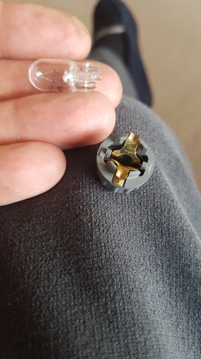
just a bulb.

Battery put on a trickle charger..

Quick message to MB to enquire about a 'new' or recon Alternator.. No Longer available was the reply.. bugger
:evil:
Nothing on Ebay either..

Helpfully after relating my breakdown saga to a Mercedes parts friend , he suggested I try a replacement Regulator, known part to fail on an alternator.. in stock.. arrived next day.
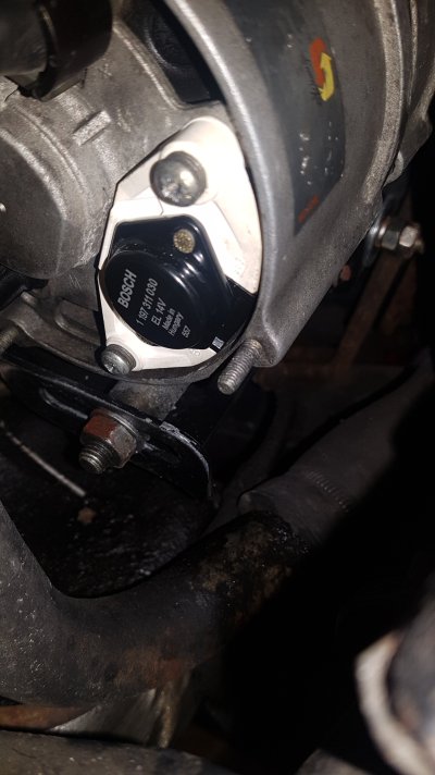
There was enough space to fit the new regulator ,without removing the Alternator... Removing and refitting is a PITA!
excellent!!.. started her up...
...err no
:?
... my test meter was still showing 11.9v output from the alternator
:evil:
!

Next day, Alternator removed from the G and dropped in at a Bosch service centre to be looked at... 3 hours later a call came from the nice man at Bosch..
" we have tested your alternator fully, and its working fine.. its putting out the correct 14v "
:?
:oops:

I told him I didn't understand, because I tested it on the G and it was only putting out 11.9v at the battery AND at the live terminal on the alternator itself.
"was the battery warning light on while it was running?" he asked.
"no the bulb has blown, I took it out and checked it, I haven't got round to changing it yet" I replied

"That's your problem then" He said "The Bulb has to be working to make the circuit, without it, the charging cycle will not be initiated" ...

Ahh... the penny finally dropped.. having No bulb (or blown one) something called an 'Exciter circuit' is not 'made' telling the alternator everything is connected and to begin monitoring the battery and charging circuit.. A BULB!!

I then began to recollect and understand more a conversation I had with my friend Mike about this problem, and the blown bulb, Mike told me not to fit an LED bulb as it wont work, it needs the circuit complete to work.. it didn't click in my brain at the time.. until I heard Mr Bosch explain it a little more.

Apparently a blown Battery warning light bulb is quite common..

I can only deduce at some point in the past the old voltage regulator had spiked the power to the warning bulb, or after 31years loyal service it had 'retired' either way I have a brand new regulator fitted (piece of mind) to my Alternator and a new bulb in my warning light,!

After a painful hour of spannering the, awkward to fit alternator, in now back in my engine bay.. The battery warning lamp lights up on ignition before starting, and goes out after, and my electrical tester says my battery is once again charging at 14v.. my rev counter is working normally again.. and after a test drive I can confirm everything is working as it should again. (I have a digital voltage meter plugged into the cigarette lighter monitoring it now!)
Who would have thought a warning lamp NOT illuminating would cause a problem!!
:twisted:


Lesson learned.... and a tiny bit more electrical knowledge gained by me... a light-bub moment!

And....I Will always check my warning lights properly from now on!

Battery warning light bulb (new)
IMG-20210507-WA0003.jpeg


Regulator on Alternator
20210507_115826 (1).jpg

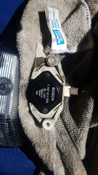
old regulator showing sprung contact brushes

20210507_112941 (1).jpg
 
Drivers seat- re-energized
:D


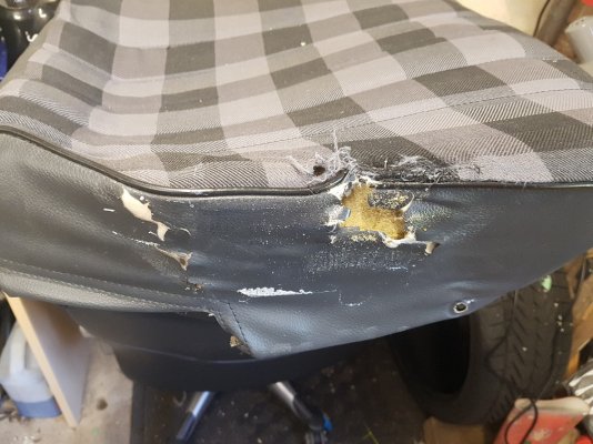
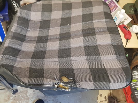
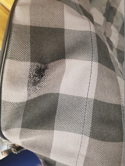
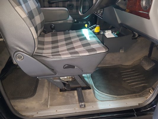
Since I had bought my 280GE .. there has been one issue that has niggled me from the beginning... that is the wear in the seat fabric and foam of the drivers seat... initially I just put some duck-tape over the hole to cover it... but as time went on I found the foam has been shedding into the drivers footwell... and the tape looked unsightly.
I have had quotes to re-trim the entire seat area in Leather.. but the cost has been putting me off...plus finding a trimmer who I could trust to do a top job...
I was lucky to have been gifted a front passenger side seat in the correct dark grey check pattern, from one of my G wagen friends.

and over a couple of days, I stripped the seats, and used the new hardly worn seat foam and covers on my existing drivers side seat.
a few adjustments were needed as I had fitted a W463 armrest into my drivers seat frame, and the seat bases differ on the drivers side with a tilt function.
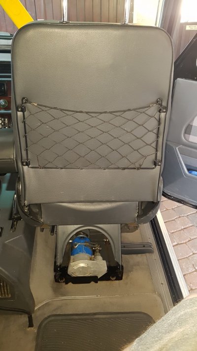
I also utilized the rear seat cargo net, which I didn't have originally...4 holes were carefully drilled in the back frame to take the screws/clips..

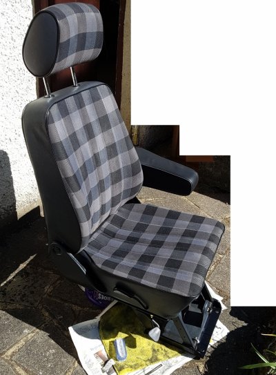
very happy with the results... the seat is now firm and supportive...where it was a little saggy and uncomfortable.... in fact it now feels like I'm sitting closer to the steering wheel..! plus it looks almost like new!...

Before (cushions removed from seat)

20180506_123756-1008x756.jpg20180506_123811-1008x756.jpg20180506_123740-1008x756.jpg

and after with a quick shampoo... drying in the sun

seat in sun (755x1024).jpg20180506_123925-1008x756.jpgIMG-af2492281db9bc52b06ef85cb876a988-V-567x1008.jpg
 
For the past few years of W460 G ownership and getting to grips with the various G eccentricities ,
one job I have always found onerous is adjusting the fan belt for the alternator so it is at the correct tension so it doesn't squeal.

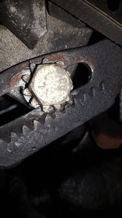
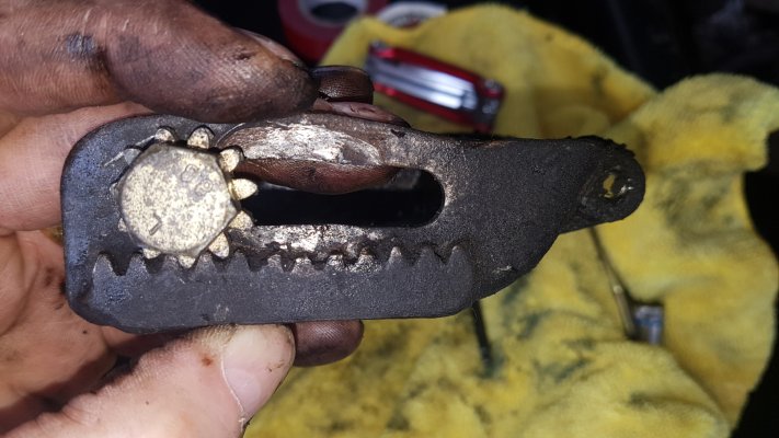
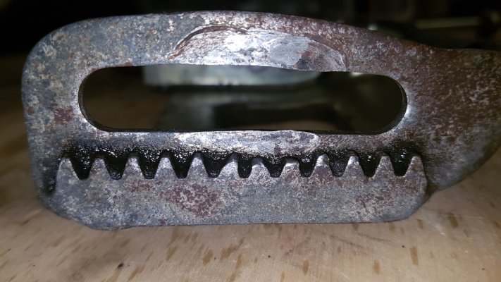
When I first got the G I found that the Star headed adjustment bolt which engages in a rack on the hanger bracket (poor design) had lost a few teeth and this made adjusting the fan belt impossible to adjust so bought a new OE Bolt back in 2014. I also fitted new belts.
This was fine for a while but eventually adjustment became difficult again. After looking at the issue I found there were teeth missing from the hanger bracket which is No Longer Available from Mercedes. One of the belts was also showing signs of wear and cracking so a replacement was on the cards too.

Adjuster teeth.jpg
I decided to modify the poorly designed adjuster with something of my own design with a view to making it simpler to adjust..
First I had to remove the alternator and its bracket to get a proper look at things as its buried deep in the engine bay on a 280GE.

Removed it and had a closer look.

20200619_110356.jpg


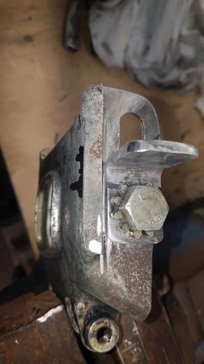
You can see the middle teeth are worn and damaged causing the star bolt to slip and making belt adjustment almost impossible.
20200619_114028.jpg

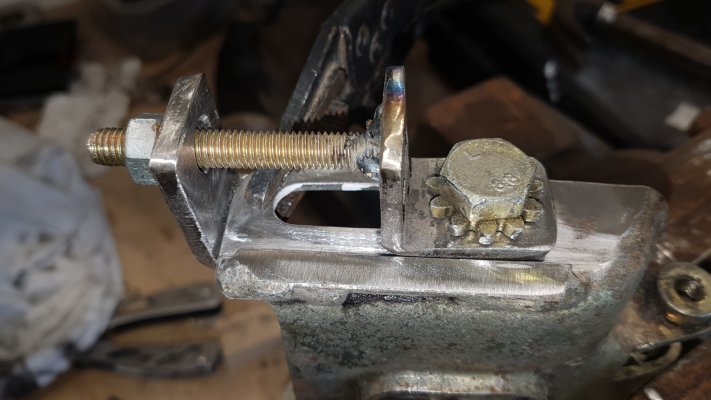
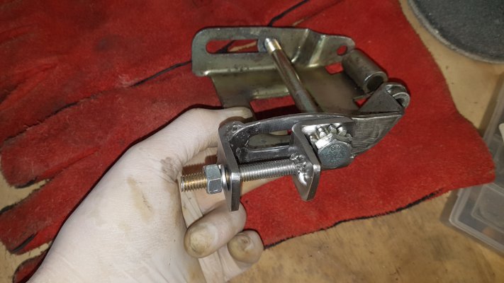
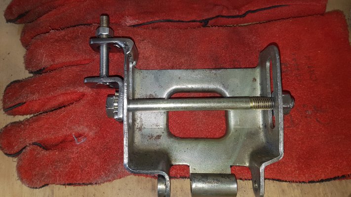
I decided to make the adjuster method with a bolt and nut... which required some modification of the hanger bracket

Marked for extraction.jpg

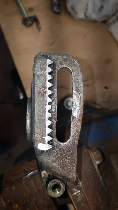
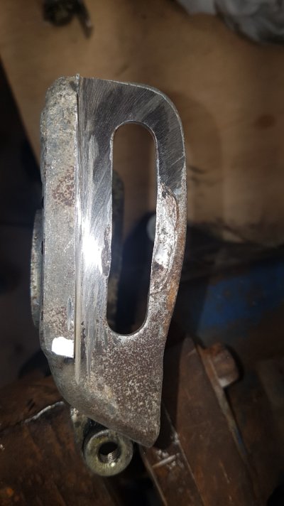
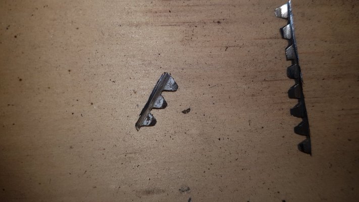
First some 'automotive dentistry' to remove the teeth!

Toothless.jpg20200619_122206.jpg

Next from 4.5mm steel I made an angle bracket to take the 10mm star bolt
L Bracket.jpg
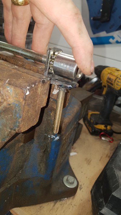
I needed enough clearance to use a socket on the bolt when completed.
socket clearance.jpg


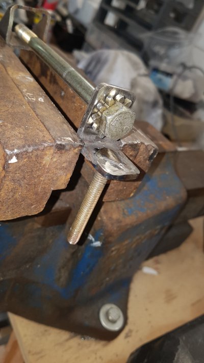
welded adjustment bolt in.jpg
next I drilled a hole in the other face of the bracket and mig welded a 8mm bolt through it,
The Longer star bolt still goes all the way through the alternator to secure it.

next I needed to see where the end plate would go for the L shaped plate to pull towards
20200619_134904.jpg

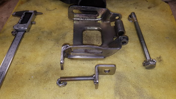
next the end plate was made from the same 4.5mm steel bent into an L shape to tuck under the end of the hanger bracket for added strength.

20200619_152203.jpg
20200619_142111.jpg20200619_151651.jpg20200619_151553.jpg20200619_151948.jpg
 
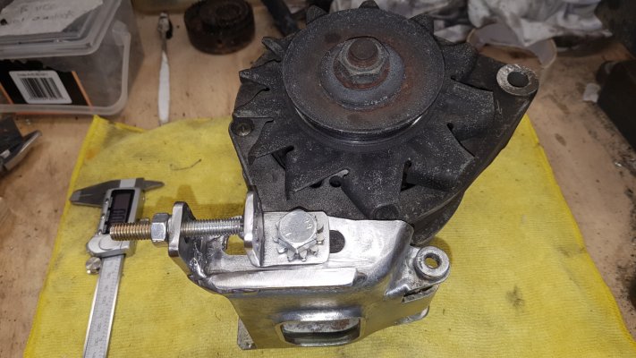
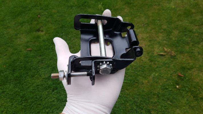
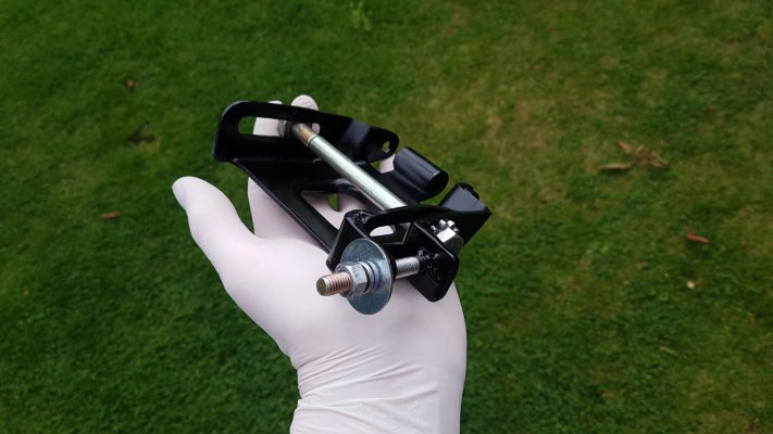
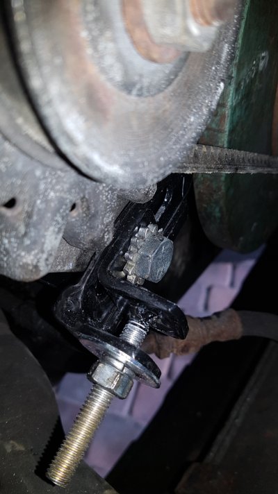
When painted and reassembled the new adjuster bolt will pull the star bolt shaft towards the end plate and hold it in position while re tightening the star bolt will clamp it in position.. thereby tightening the belt of the alternator.

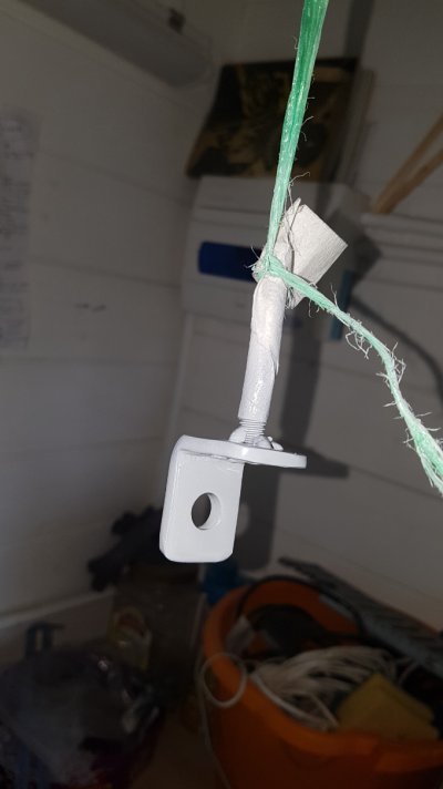
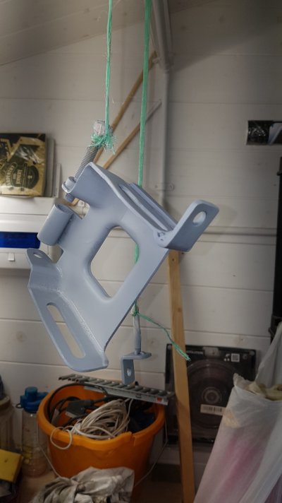
etch primer
primer 2.jpgprimer 1.jpg

gloss black

20200620_103705.jpg20200620_103709.jpg

fitted and working
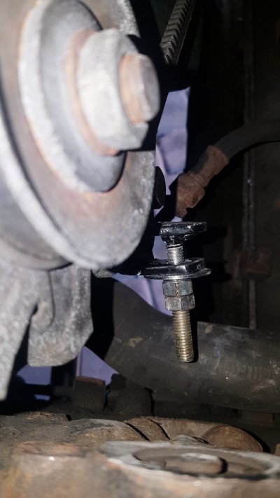
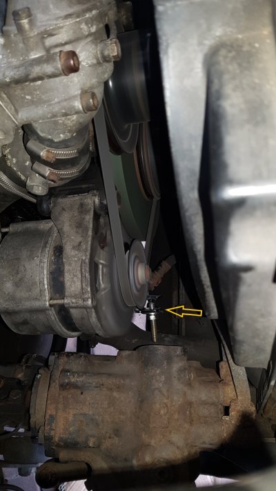
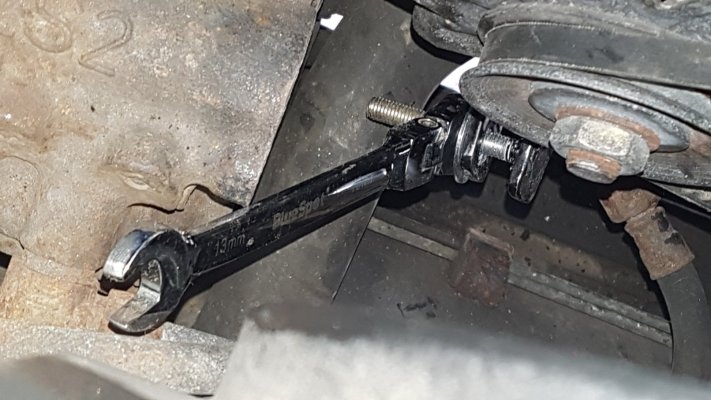
20200623_114503.jpgEasy access Adjuster.jpgFitted bracket and new adjuster.jpg20200620_123703.jpg

Much easier to adjust belts. then retighten the long star securing bolt.. and mount bolt... I added a locknut to the final version.
 
Great project and I'm doing an engine swap on my 40 year old Benz so thanks for all the pictures, suggestions, tips and tricks!
 
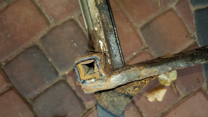
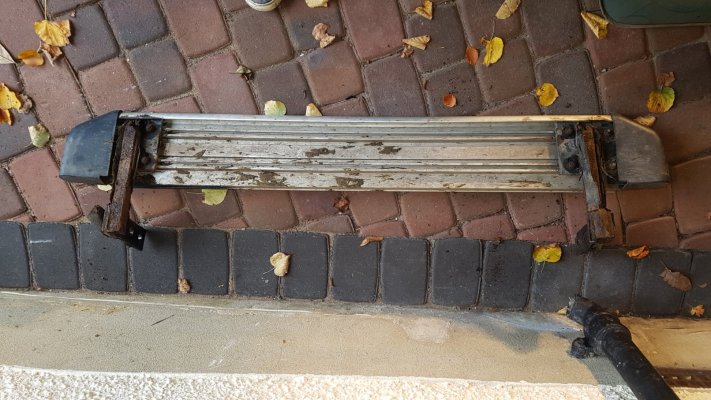
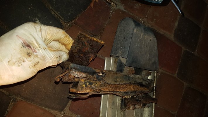
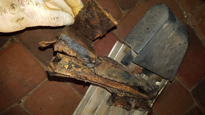
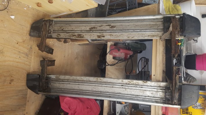
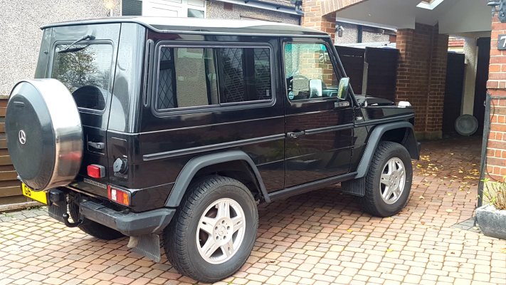
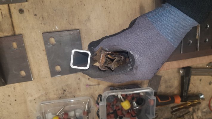
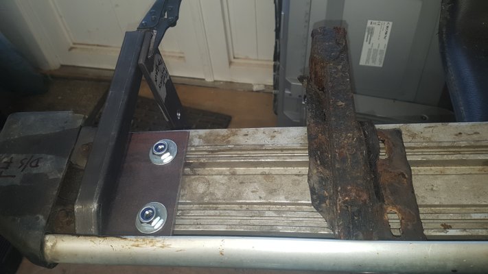
During my recent overhaul I had my attention drawn to the rusty side step brackets on my non oem side steps... that had reached the end of their serviceable life. The powder coating, had burst open and the 'puff pastry' effect of delaminated rusty metal layers was a common theme on the brackets...
So time to get some new ones.
:roll:

I contacted a seller on eBay who was selling the same style steps as mine and asked if he sells the brackets separately ... sure came the reply £155
:shock:

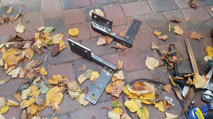
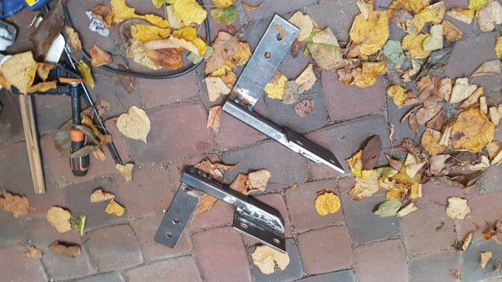
They are basically a piece of 8mm plate steel with a piece of box section welded on and another piece of 6mm plate steel where the step bolts on.. plus some new bolts and a lick of thick paint, two brackets per step. Seemed a little expensive, plus the delivery time was unknown as they would be made to order
:shock:


So being impatient I thought.. I can weld.. I will make new ones!
:P

I sourced some steel locally and ordered new zinc coated bolts nuts and washers...

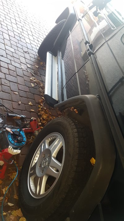
This was the state of the step brackets (the steps themselves are aluminium )

20201029_120100.jpg20201029_120114.jpg20201029_125538.jpg20201029_125546.jpg20201101_160042.jpg

I quite like the look of the G without any steps on.... that news wasn't received too well by Mrs757... who due to her 5'2" height needs a step up!
;)


20201030_164305.jpg

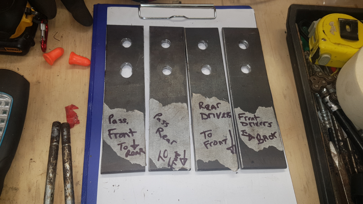
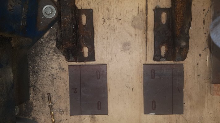
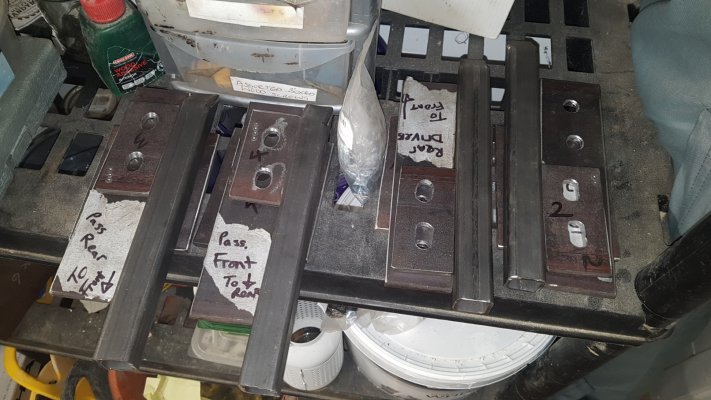
I set about making new brackets for my steps ... each bracket is different and the body mounting holes were drilled by the previous/original owner in slightly different locations as they used the slotted hole as a guide
:roll:


I used 8mm plate steel cut to size with an angle grinder and drilled to match the existing holes of the part that mounts to the body.
20201101_151503.jpgdriver front.pngbody bracket.png

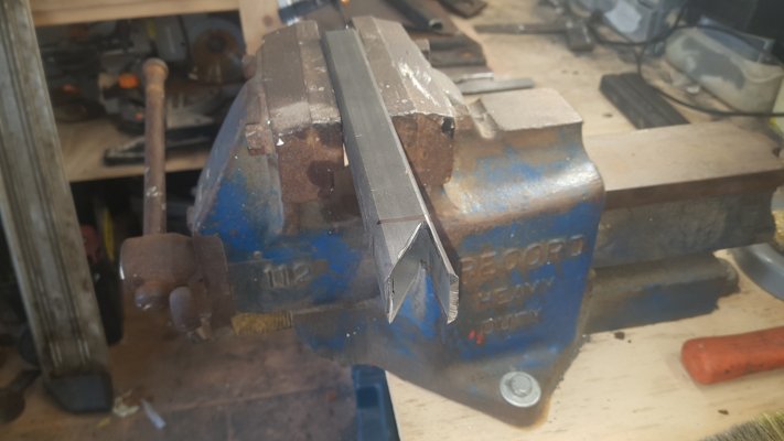
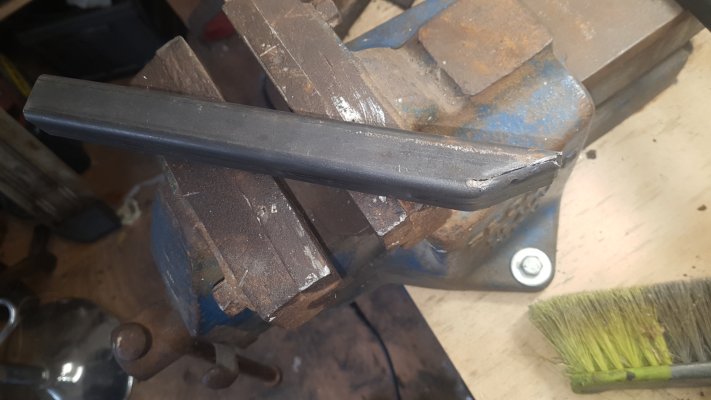
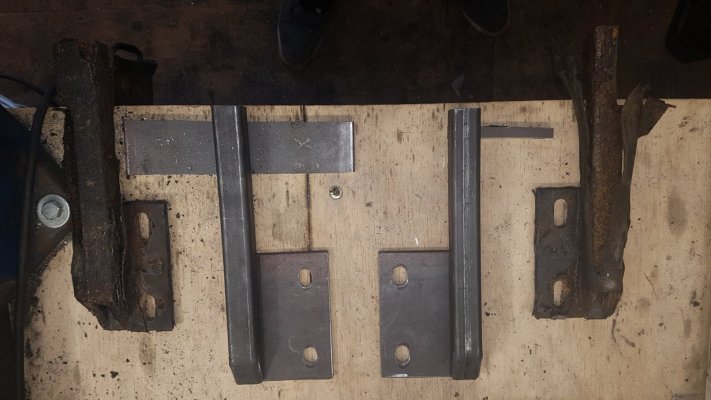
Next I cut the 25x25x3mm box section to length. The original brackets had the box section open the the elements.. on my new modified brackets I will weld plates over the ends to keep the corrosion at bay.

20201103_141814.jpg20201103_115941.jpg20201103_120643.jpg

this cut will be welded closed as well as a square plate welded into the other end

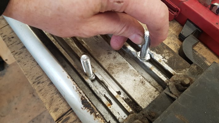
The step mount plate was then cut from 6mm steel plate.. this was extended by 25mm so that the bolts that slide into the alloy step groves were in a new position, where the grove is undamaged. It became necessary to cut the old corroded bolts off.

20201103_114817.jpg20201103_141716.jpg20201103_141831.jpg

and drilled , I bought new zinc coated bolts/nuts/washers ,

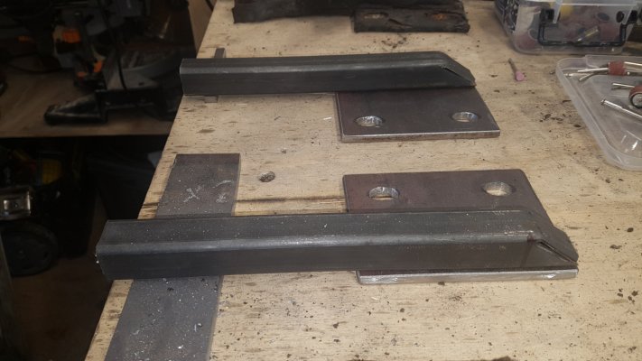
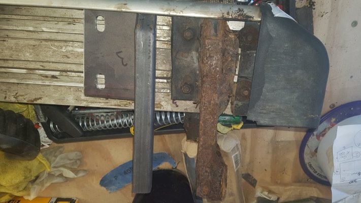
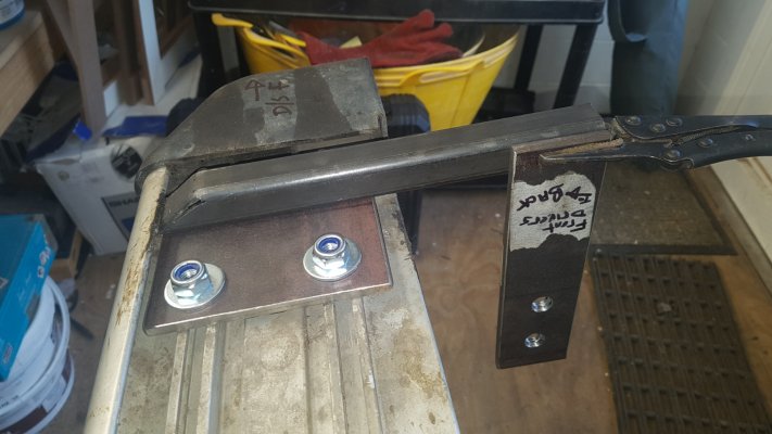
I then mocked up the bracket positions

20201103_152314.jpg20201103_143418.jpg20201103_143336.jpg
 
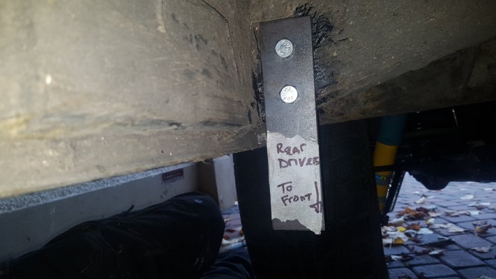
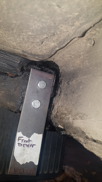
There were also 4 small plates I cut from 6mm steel plate that go on the opposite side of the body mounting point and act as load spreading washers .
Brackets all made... next job will be to weld them together to form the 4 brackets... had to wait for some new step attachment bolts to arrive.
20201103_172455.jpg

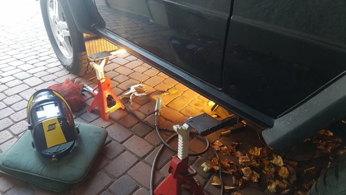
Brackets mocked up on the car, then tac welded.. later followed by final welding

20201106_150341.jpg20201106_143500.jpg20201106_143458.jpg

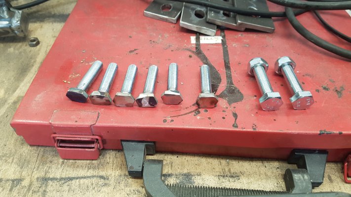
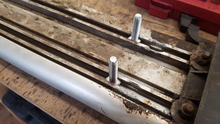
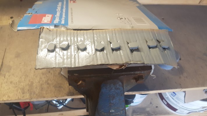
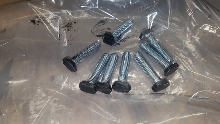
I modified some 10mm bolts to go into the retaining slots that secure the aluminium steps to the new support brackets.. the two bolts on the right are how they started. (the apparent holes are where the old bolts wore the aluminium away forcing me to move the bolt positions.)

20201107_121900.jpg20201107_121903.jpg20201107_121921.jpg20201107_141307.jpg20201109_103238.jpg

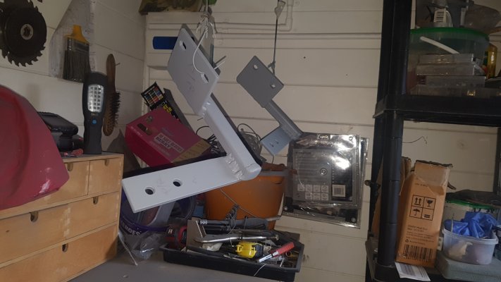
Brackets welded... etch primed
20201107_143726.jpg20201107_143741.jpg20201107_143745.jpg

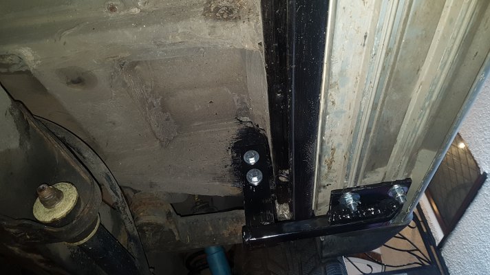
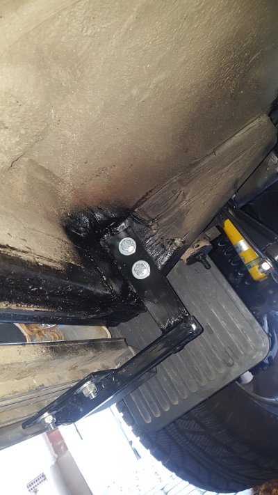
Step Brackets Painted and fitted... with new zinc coated bolts n Nyloc nuts.. with an extra coat of underseal to make sure it stays non rusty! all Finished
:)


20201109_114916.jpg20201109_114932.jpg20201109_114904.jpg20201109_131408.jpg
 
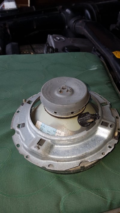
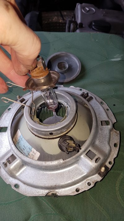
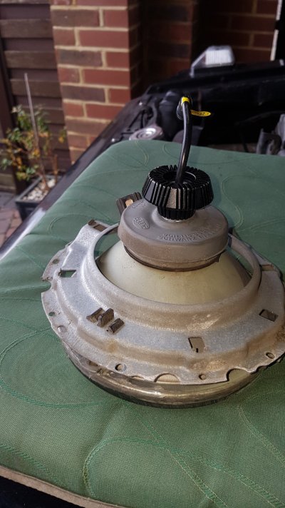
32 year old H4 Headlamps.. upgrade to LED Bulbs.

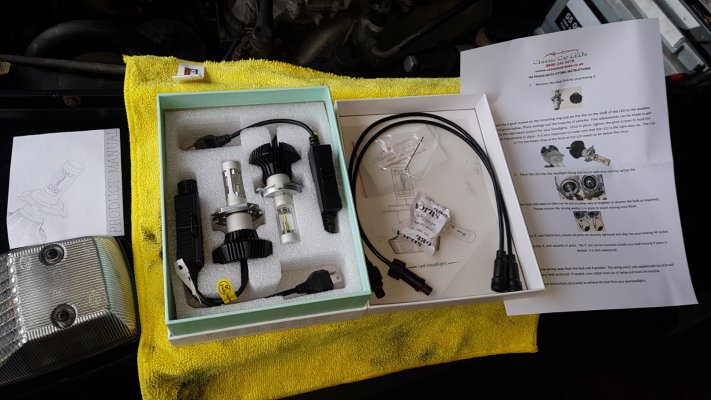
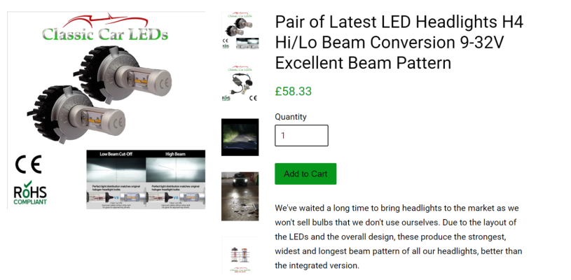
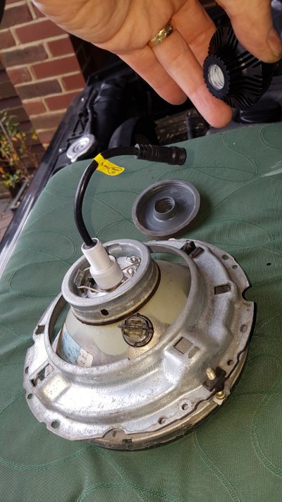
I ordered a pair of these new H4 LED Bulbs to go in my standard W460 headlamps..
from http://www.classiccarleds.co.uk the same people i bought my dashboard LED illumination bulbs from.

They cost £58.33 plus VAT per pair.. (Free UK Postage) and come CE marked and have a 12 month warranty.

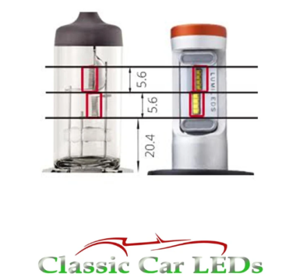
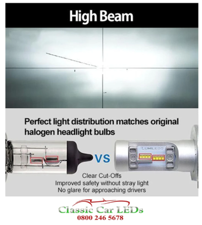
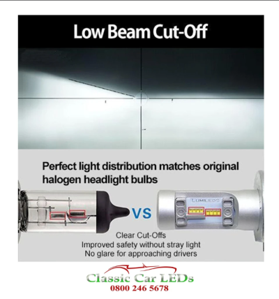
I was impressed that unlike some LED bulbs they are specifically designed to mimic the dipped and
high beam patterns of the standard bulb to prevent dazzling oncoming drivers, despite being much brighter.
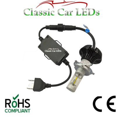
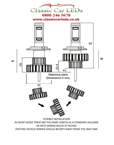
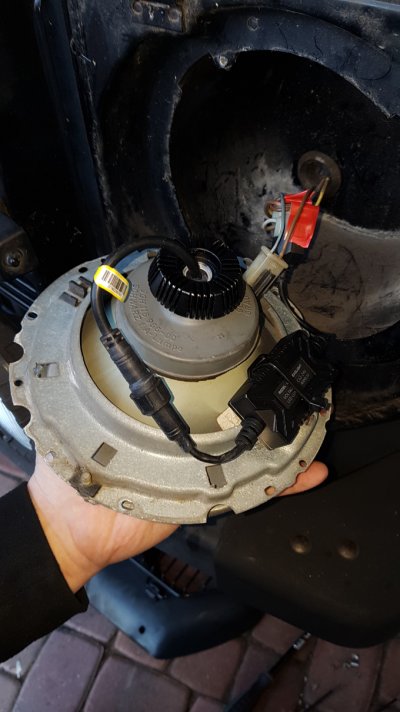
It comes with a small control box which should fit behind the light, but as a precaution ordered a pair of extension plugs in case this needs to be positioned in the engine bay. (£2.50 each plus VAT) and retains the OEM headlamps and look.
(depending on the year of your car these might not be MOT compliant)
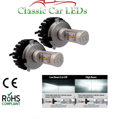
The following are pictures and descriptions from the Classic Car LEDs website.
20200117_121746.jpg
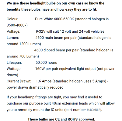
LED H4s.pngLED H4s Wires.pngLED H4s Dimensions.pngLED H4s High beam pattern.pngLED H4s Description 1.pngLED H4s heatsink.pngLED H4s Description 2.pngLED H4s Description 3.pngLED H4s Description 4.pngLED H4s Description 5.png
The company Classic car LEDs have been easy to deal with , and respond to emails and questions quickly
The product was well packaged and appears to be of high quality
I am very happy with the result!
12 month warranty on bulbs and CE marked.
H4 G wagen LED Sidelight bulbs are BA9S 233 989 and were only £4.42 each plus VAT

Very Impressed with the quality... LED can be adjusted (beam) to suit individual cars.. Most in the UK are set the same...( Also works in LHD vehicles)

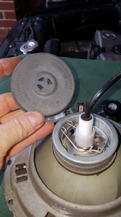
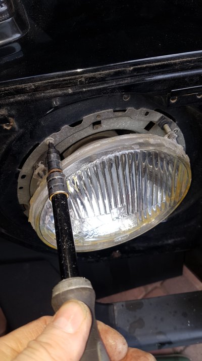
Simple to fit, only the hole in the headlamp rubber bulb cover needed a tiny trim...
Heatsink must be removed before fitting.
Bulb must be fitted with the little caps below the forward chips on the bulb (Low Beam) otherwise the dipped beam will not be correct.
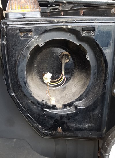
plenty of room behind headlamps for the small control box.. and the heat-sink on the rear of the bulb. The supplied lead connects to old bulb block connector. extra extension leads I ordered were not required. The control box is small enough to go in the headlamp bowl, cable tied to the headlamp fixing bracket so it does not move freely.
20200117_122123.jpg20200117_122320.jpgLED4.jpg20200117_123230.jpgLED5.jpgLED2.jpgLED1.jpgLED3.jpgLED h4 Beam dipped.png
 
Last edited:
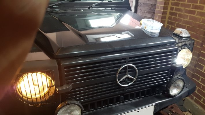
The difference was Amazing.
Took the G out to road-test the new LED headlamps... very impressive... good wide beam spread... sits below rear window of cars I'm following.. crisp clear white light.. excellent on dipped... and very fast reaction of main-beam... milliseconds as opposed to half a second of the filament bulbs... no dazzling of other drivers.. no angry flashes from oncoming cars... overall.. I would say with new LEDs in 30 year old headlamps.. I am very happy with the outcome...

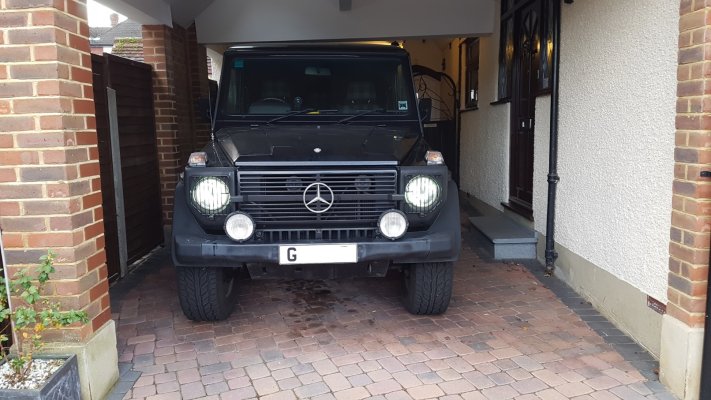
Side lights LED
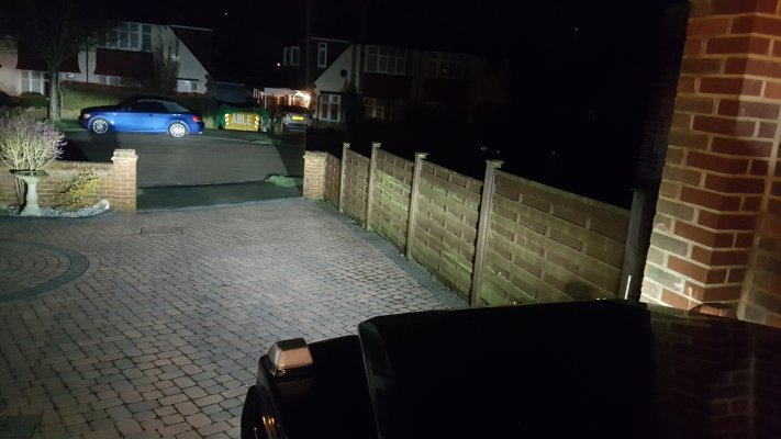
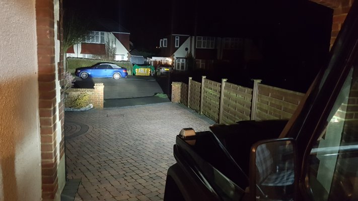
20200117_141635.jpg

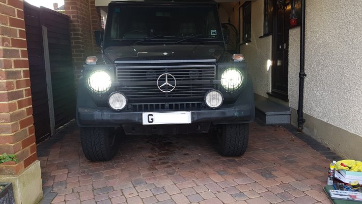
Then Dipped Lights
20200117_130339.jpg

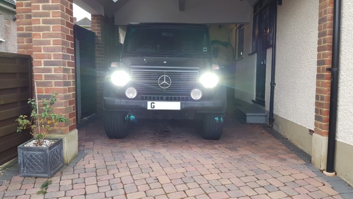
Then Main beam
20200117_141724.jpg


Dipped
20200118_045214 dipped.jpg


Main Beam20200118_045231.jpg

Drive drops away a few feet...

I spoke to Classic car LEDs negotiated a small discount for members of 5% on purchases of any LED bulbs from their company.
Quote reference gwagen5 at checkout where it asks for a discount code.


This is a comparison of the std sidelight bulbs verses the LED ones.....

20200108_113807.jpg
 
Last edited:
Great difference, will be interesting to see how it will fare at MoT time...
 
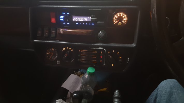
Time will tell... I also upgraded the dashboard from its weak 1980s illumination to LED.
I found a UK company who have been very efficient and helpful with next day postage if ordered before 1pm (Details below)
This is for a W460 model mine has a Tacho.

First remove the rear of the instrument binnacle by removing the two small screws on the sides, to gain access.

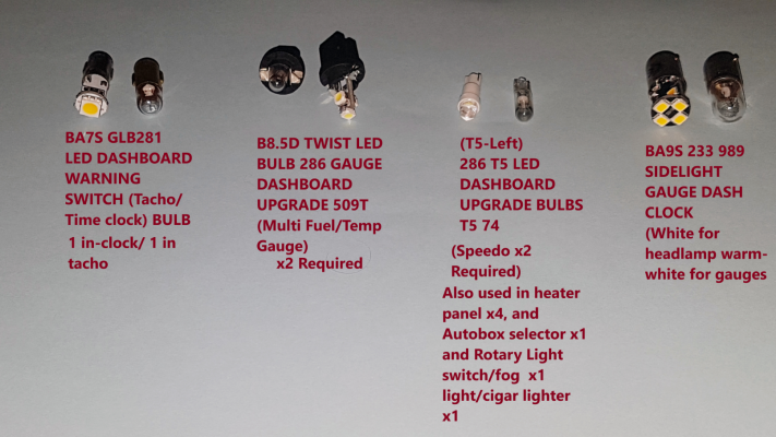
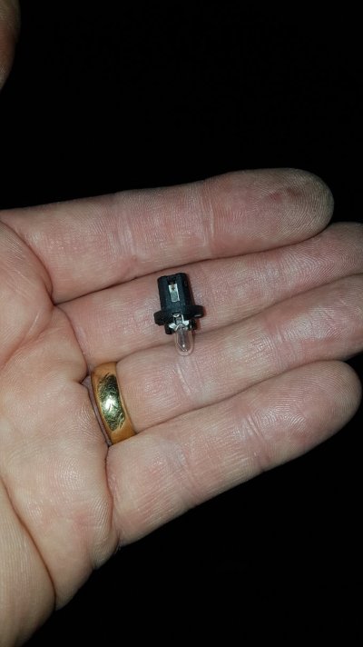
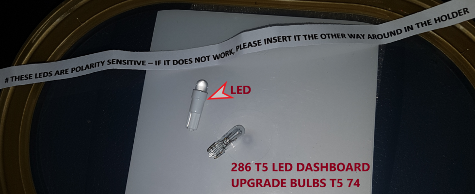
These are the Bulbs I have used.

LED Bulbs upgrade.png
 
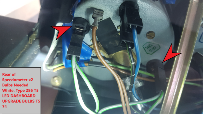
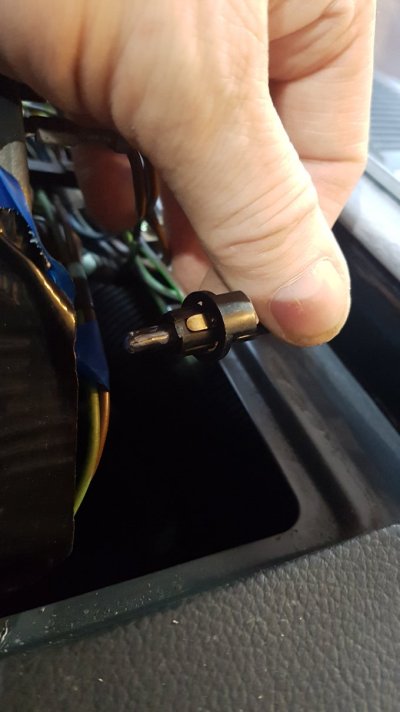
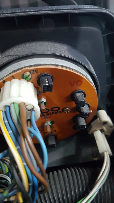
Starting first with the Speedometer... pull the two bulb holders gently to the rear and replace the bulbs with the push fit LEDs... check they work as they only work one way round.
Speedo LED Upgrade.png20200108_103551.jpg
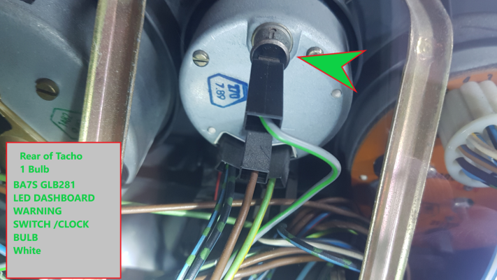
next the Tachograph which has one bulb.. and is fitted in a spring loaded holder... pull to rear to remove the holder and push and twist the bulb to remove it. Then replace the holder , the bulb only goes in one way.

Tacho LED Upgrade.png
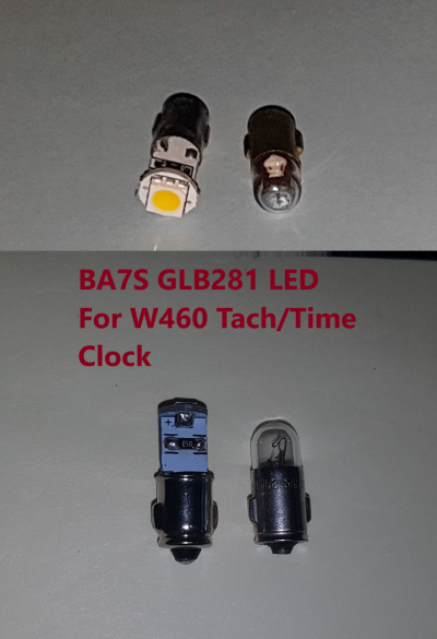
Tacho LED Bulb.png

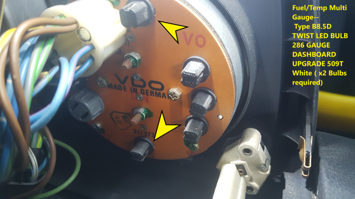
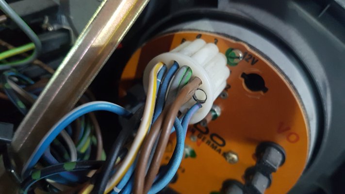
Next is the push and twist bulbs in the rear of the Multi Fuel/Temp Gauge, of which there are two one top one bottom.
Multi Gauge LED Upgrade.png
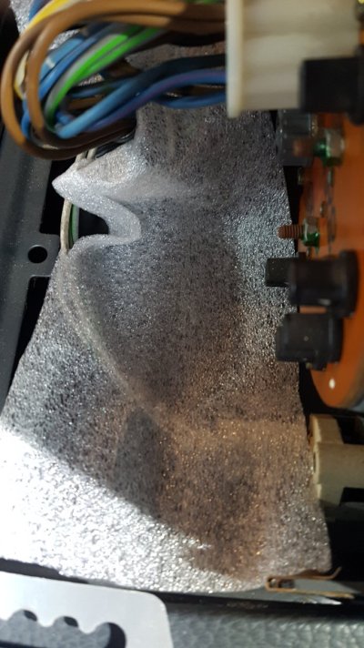
I found the replacements a little tight so I finessed the gap of the locking tab a little with a small screwdriver- also remember which way you turned it... and put a cloth or similar under the back of the gauge to stop any dropped bulbs disappearing behind the dash (ask me how i know!)

20200108_104332.jpg
20200108_103635.jpg20200108_103646.jpg20200108_104057.jpg

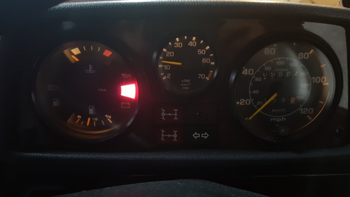
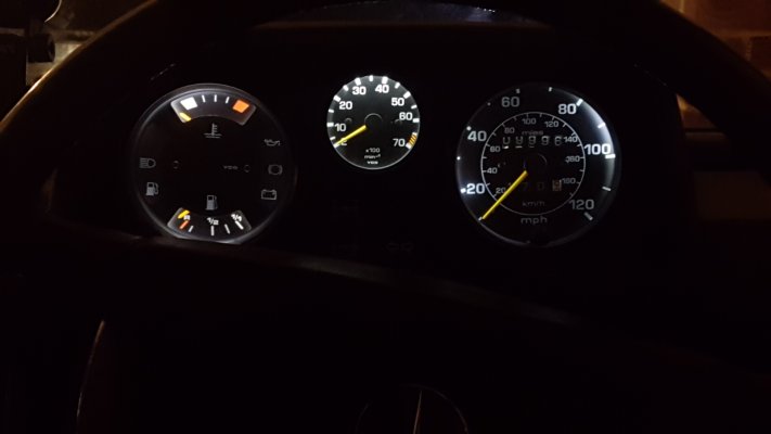
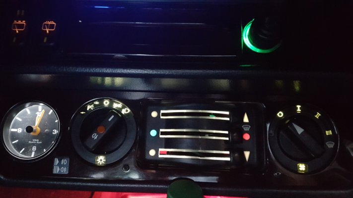
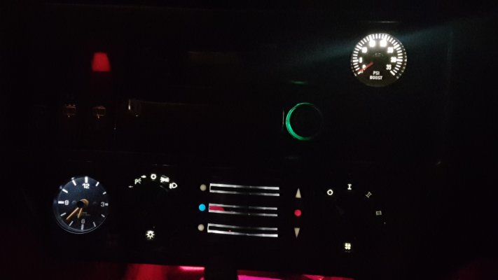
This is the before and after... the camera struggles with bright light in the dark.. the gauges are clear and not too bright. much better than original.
Before:
20200108_093504.jpg

After:
20200109_183857.jpg

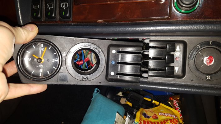
Next replacing the four T5 bulbs in the heater panel
20200108_100420.jpg20200108_100641.jpg20200108_101919.jpg

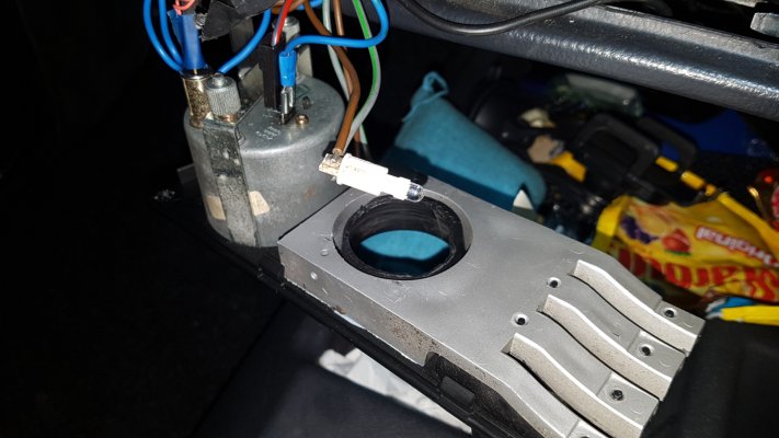
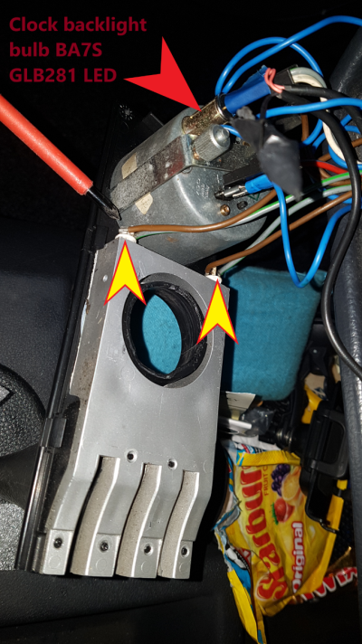
While the heater panel is off... you can remove the bulb holder in the rear of the Analogue clock marked and replace old bulb with a BA7S GLB281 LED
heater panel bulbs2.png


The panel locks together in the middle by fingers and slots

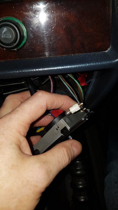
once you have removed the panel you will see wires going to the bulbs at the end (arrowed) these are just push fit holders.
carefully pull out and replace bulbs (push fit also) check they are in the right way round (they only work one way) by turning the lights on briefly.

T5 LED (1).png

Heater panel/clock before

20200108_093454.jpg

After

20200109_120447.jpg20200109_183908.jpg
 
Amazing difference to the dash lights and this is a fantastic thread and worth its weight in gold for any G wagon owner. Well done !! 👍

I'm sure if you were in the official owners club they would publish many of your repairs / mods in their Gazette.
 

Users who are viewing this thread

Back
Top Bottom