350_Coupe
Active Member
ok, so I made this repair a long time ago, and simply forgot to compile this how to guide, so here goes and hopefully it'll be of some use to someone in the future.
Couple of points to note before I get started
My mirror frames and wiring are different per side as is standard, however I have a left hand drive n/s frame so that i can have the dimming function as well, and the frame I bought has the wiring for memory as well, your car will likely have different configurations between the two sides, but unlike mine, you'll have less wiring on the n/s not more!
Firstly, lets have a look at the problem....
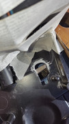
These are all indications of this problem, although of course it could also be the switch pack or other wiring issue, so first thing to do is remove the cover and have a look (this is done by folding the mirror in and using a flat blade screwdriver to release the cover clip and slide the cover off, you may need to push the mirror manually in at the hinge end to allow the cover to slide off, the process can be seen here
and
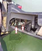
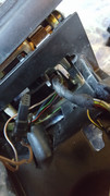
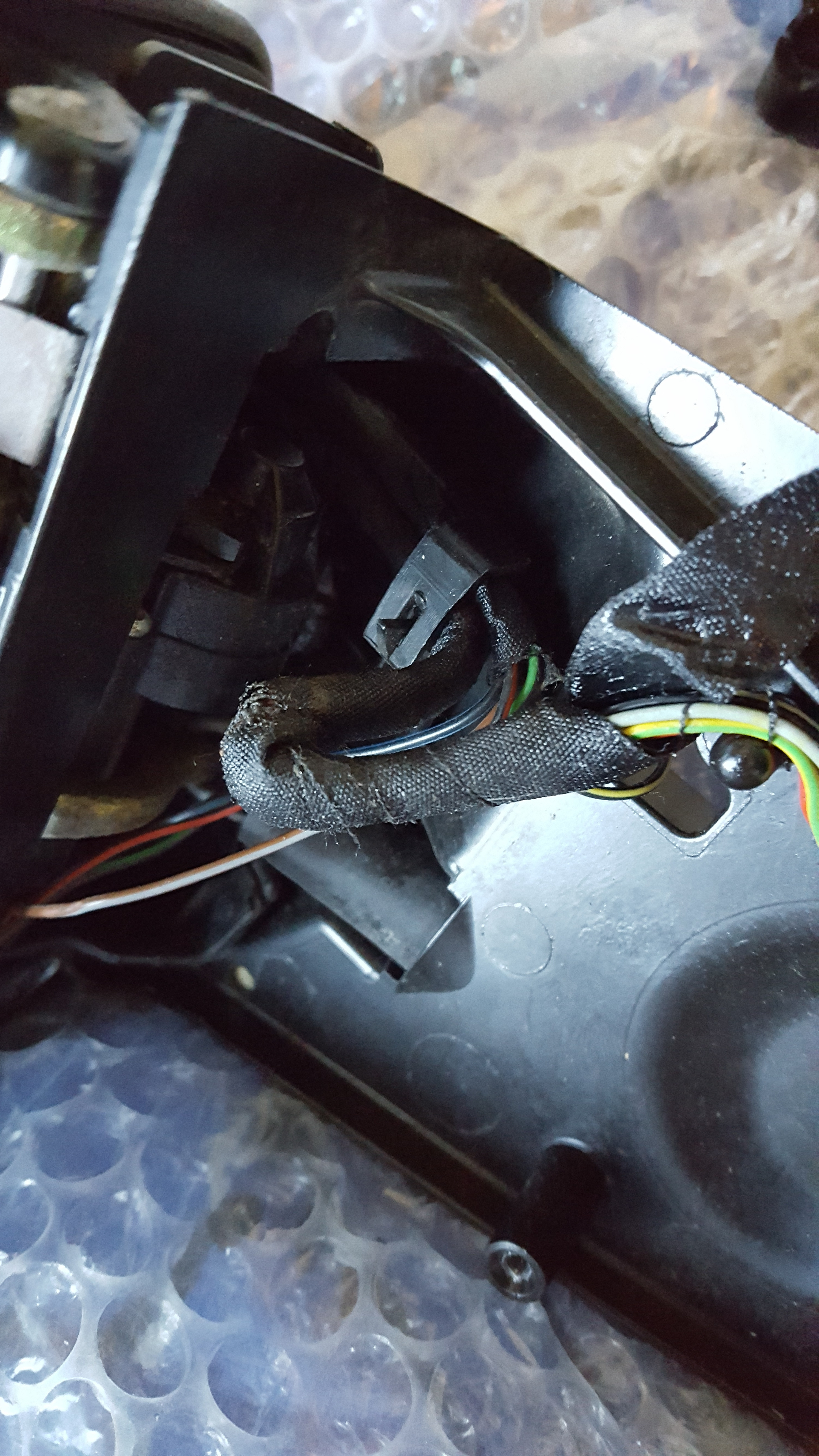
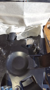
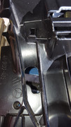
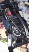
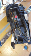
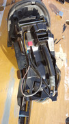
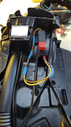
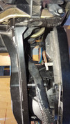
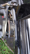
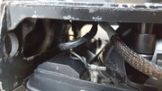
Now lets see if you are likely to have this problem, in the images you can see the problems highlighted.
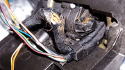
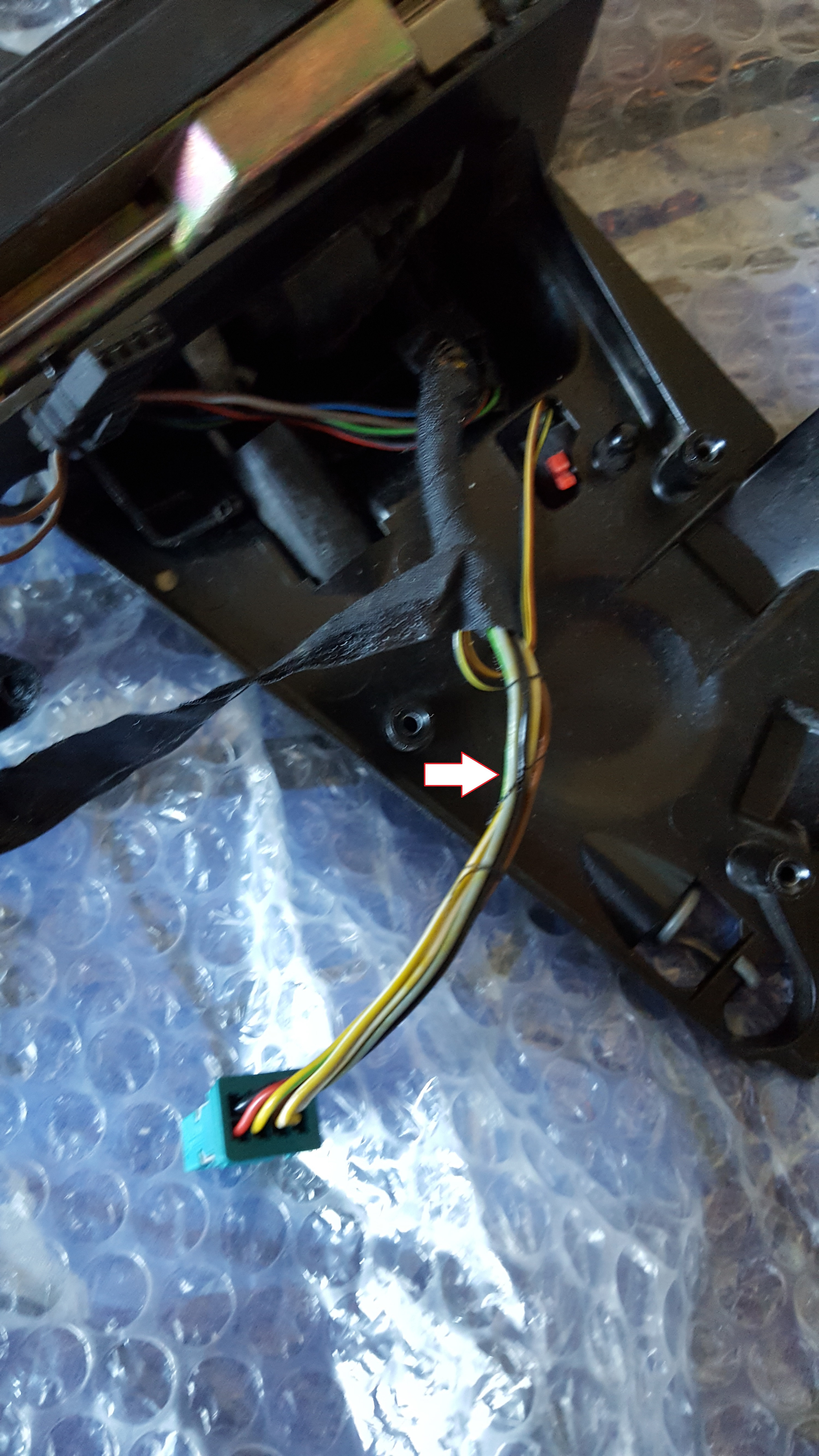
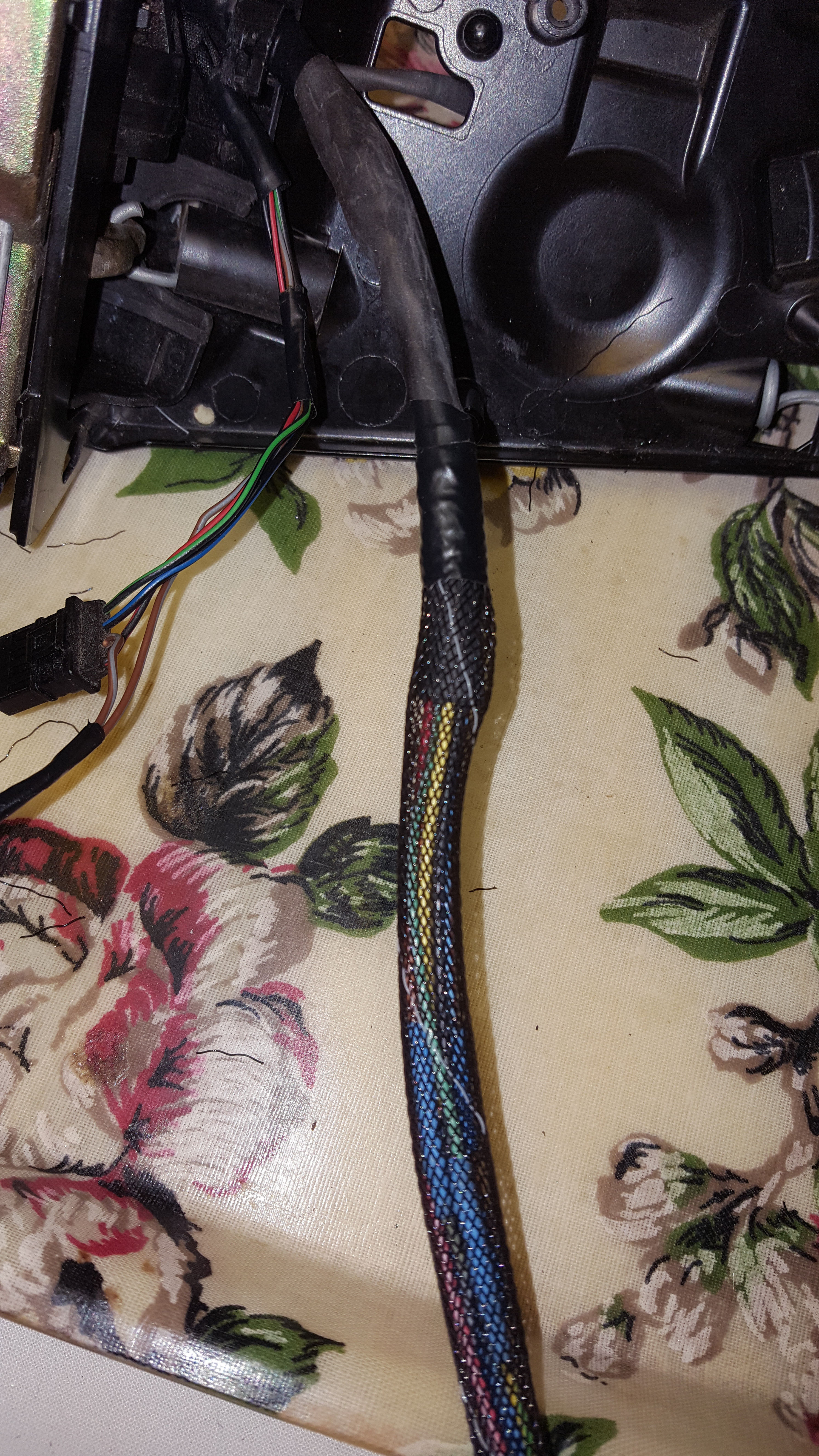
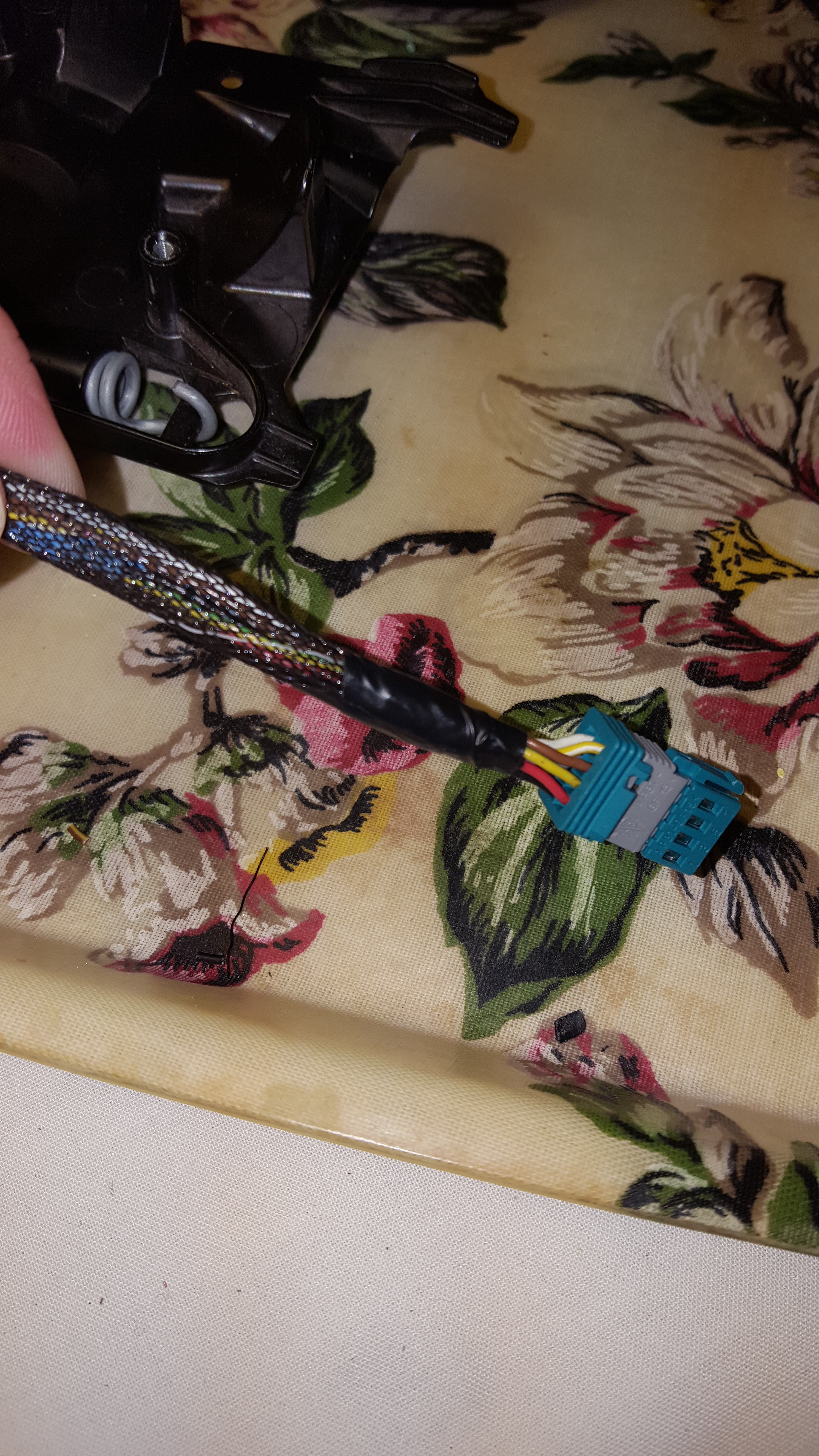
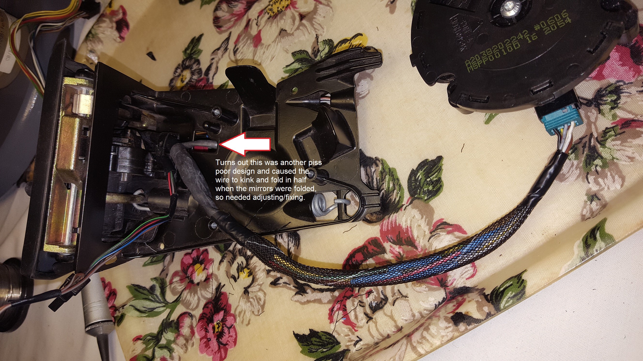
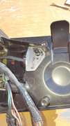
Picture 1 - excessive bend is visible with damage to the wiring wrap, after you remove the mirror and unplug this loom you will notice it's really weak at this point, and hinges where cable breaks are
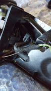
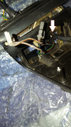
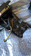
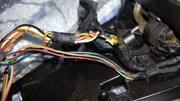
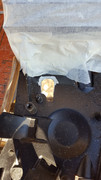
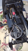
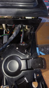
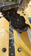
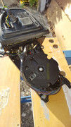
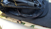
Pictures 2 through 4 - show the same bend that is the problem. (image 2 also shows the heating element wires, also crimped by bad placement when fitting the glass)

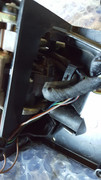
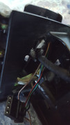
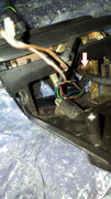
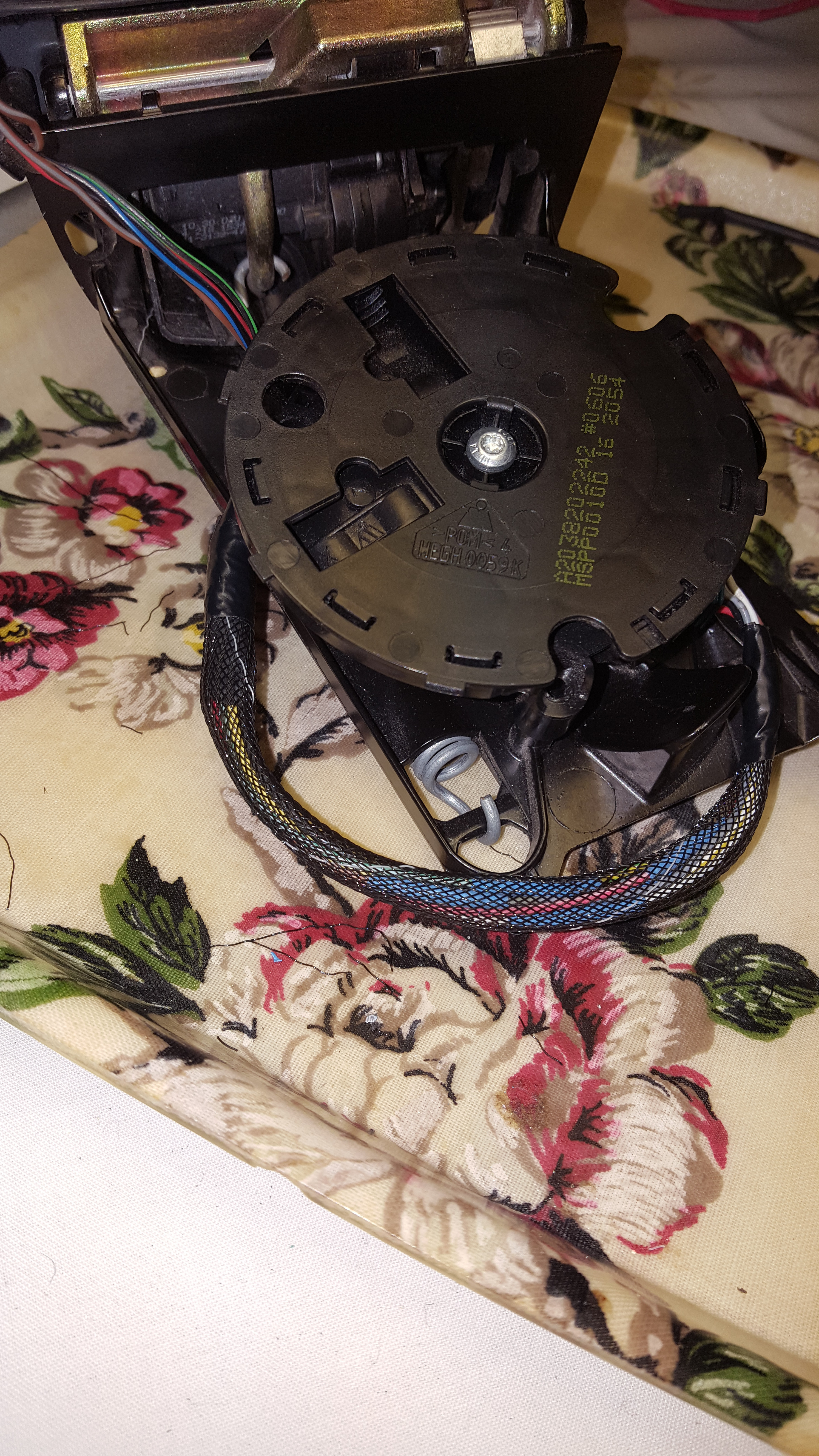
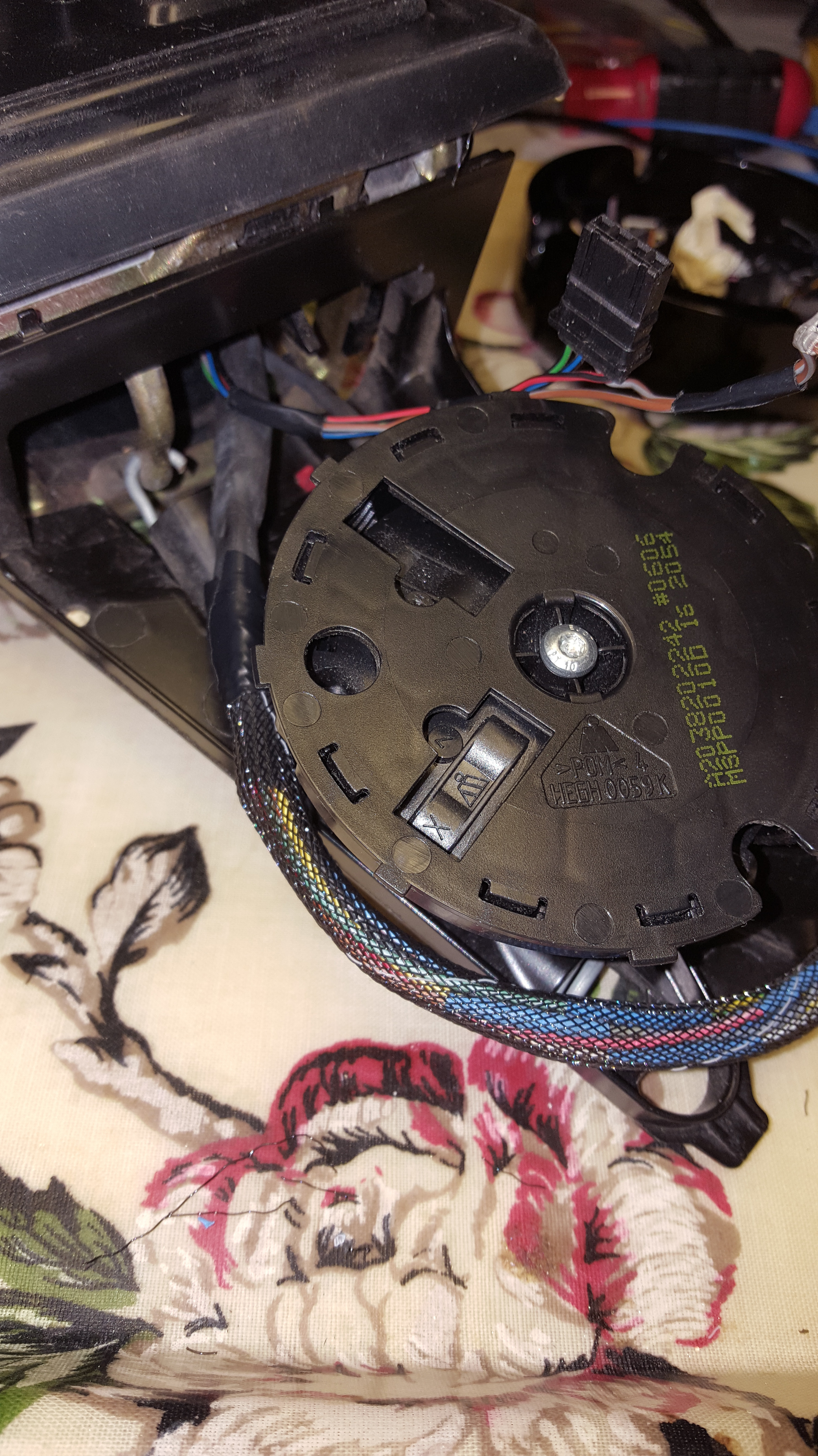
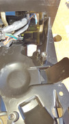
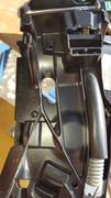
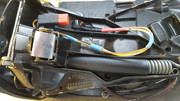
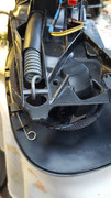
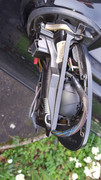
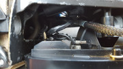
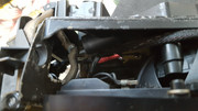
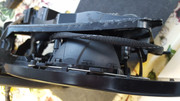
Pictures 5 through 8 - show the wiring with the mirror frame in various stages of folded, and you can see the toothed gear arm in close proximity to the loom
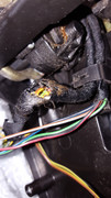
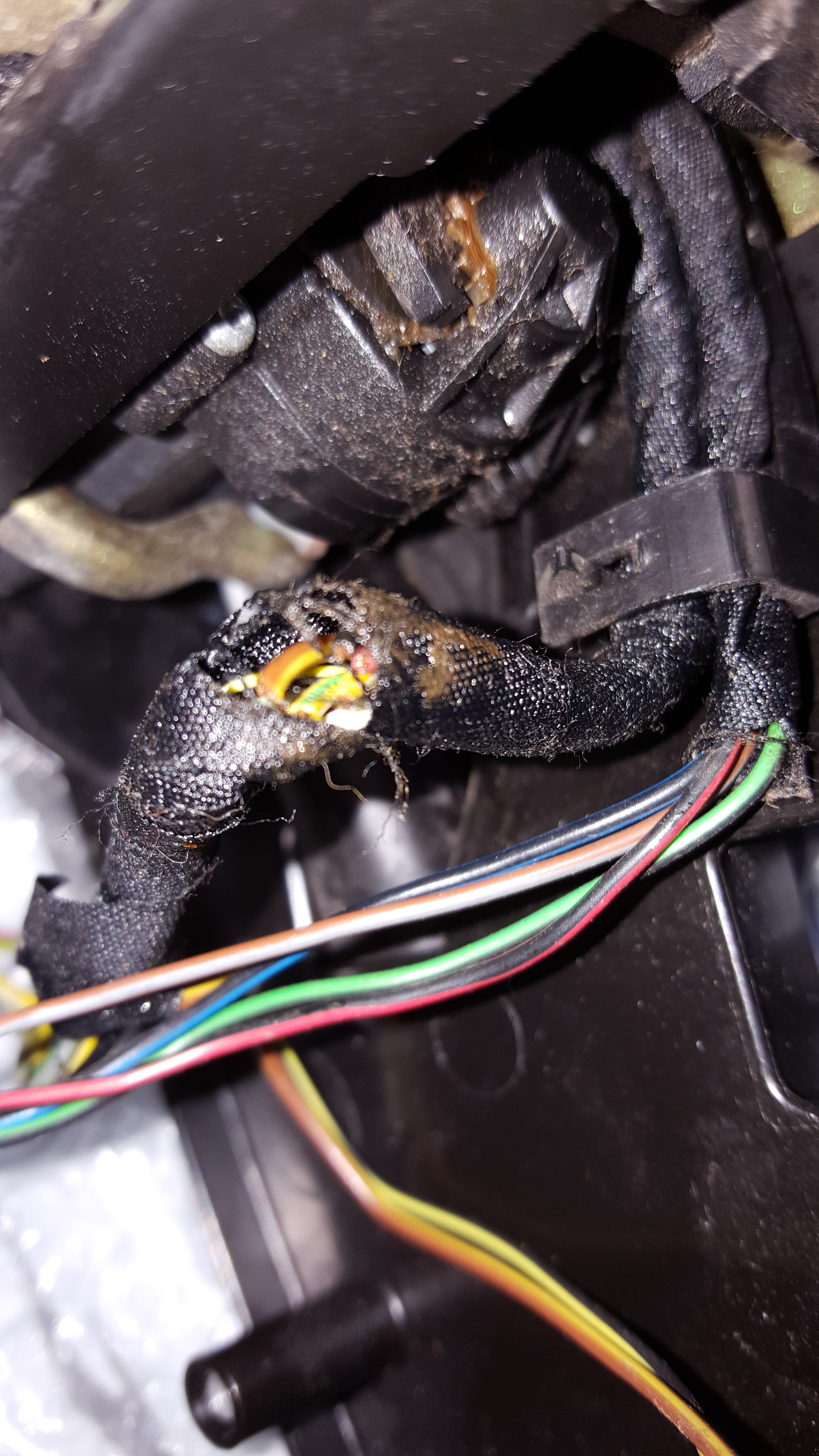
Pictures 9 and 10 - show what that toothed arm does to the loom wrapping
At this point if you are sure the problem lies in the frame wiring, you're going to want to remove the whole mirror unit from tthe car, it would be a lot harder to fix in situe, i'm not going to go into that process here, lots of videos on you tube for that if you can't work it out, beware of the likely need for a 5 point torx-plus drive bit to remove the frame from the car, unless you've had a helpful garage change it in the past and put regular allen key headed bolts in there when putting it back (PCS - thank you ollie)
So, once you have it off the car and start stripping it down, the problem becomes very obvious!
Pictures 11 + 12 - not so obvious in the image, but the cable may be broken at the arrowed points and when you hold it and flex it, it 'hinges' rather than bends in a loop

Picture 13.... ah the one that was literally sawed in half!! only thing holding that together i think was one wire and the fabric wrap!
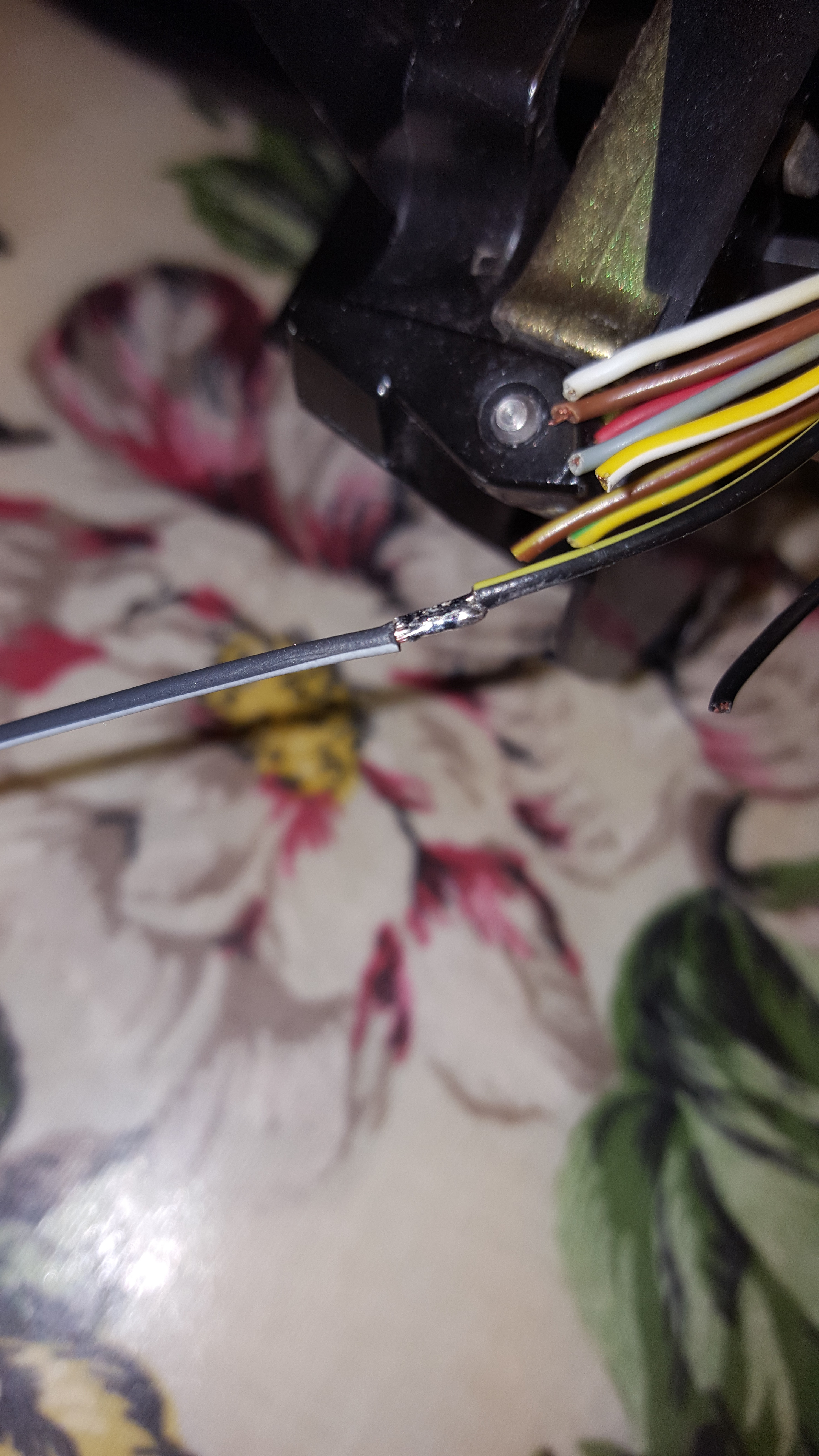
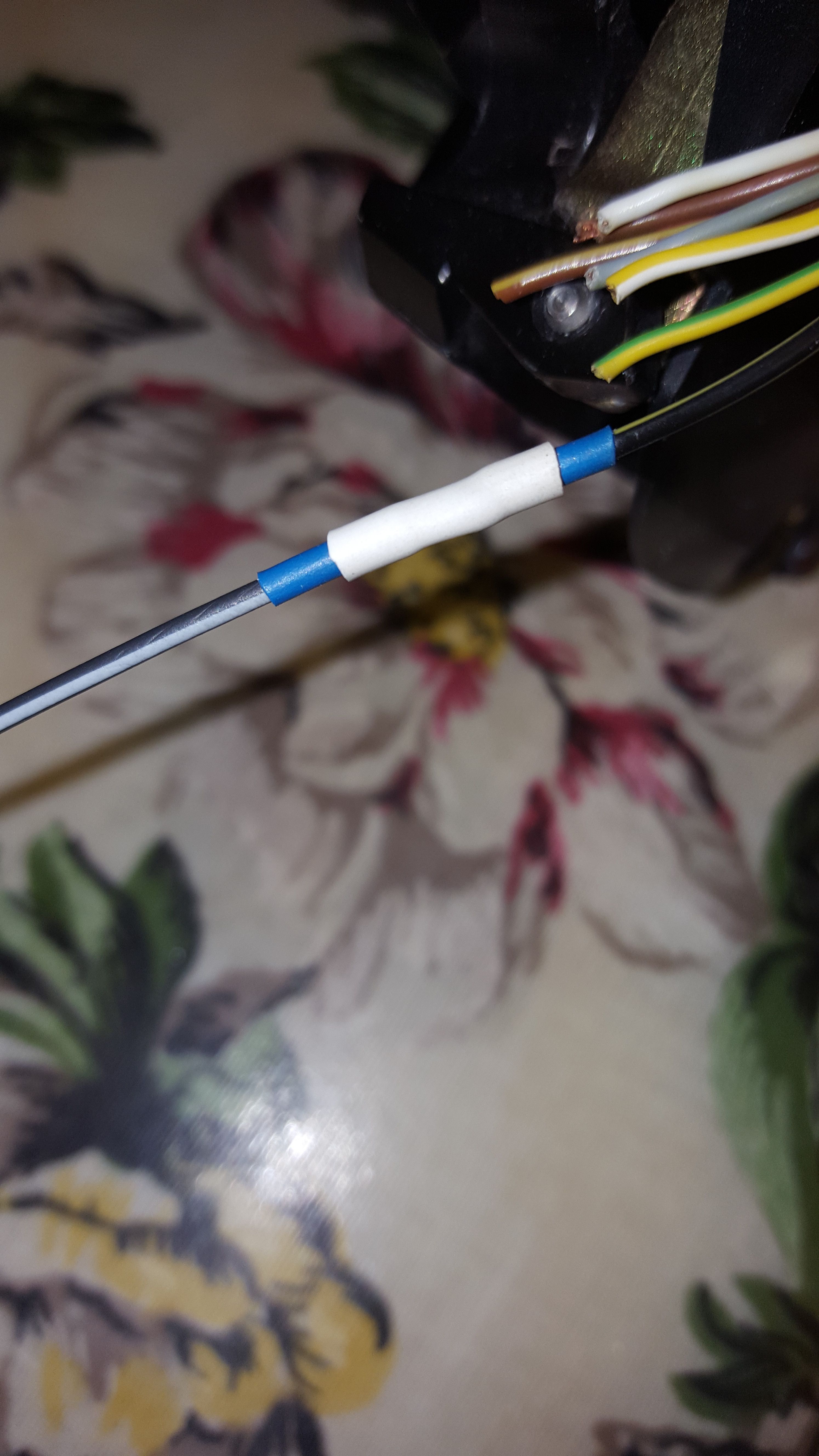
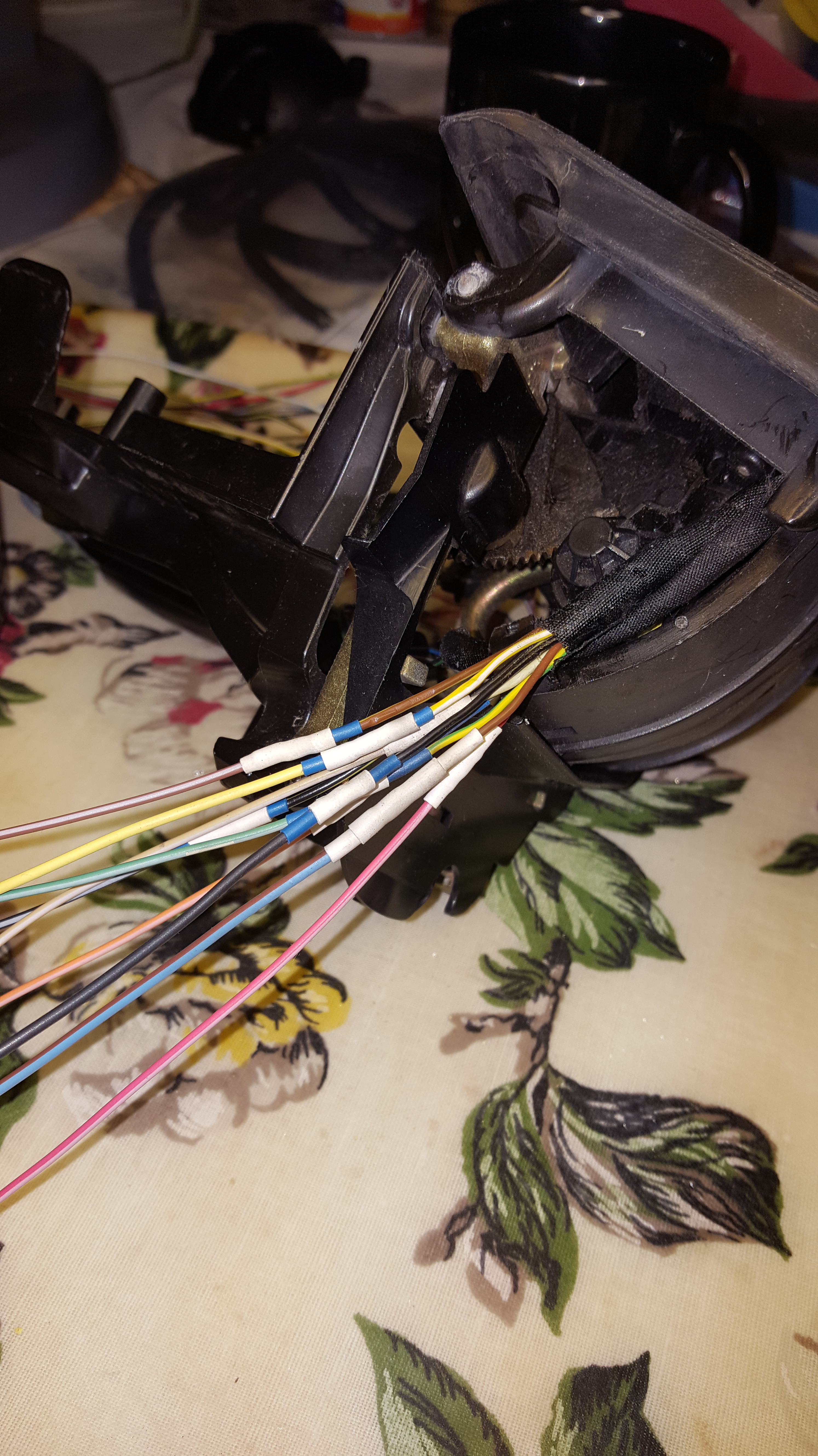
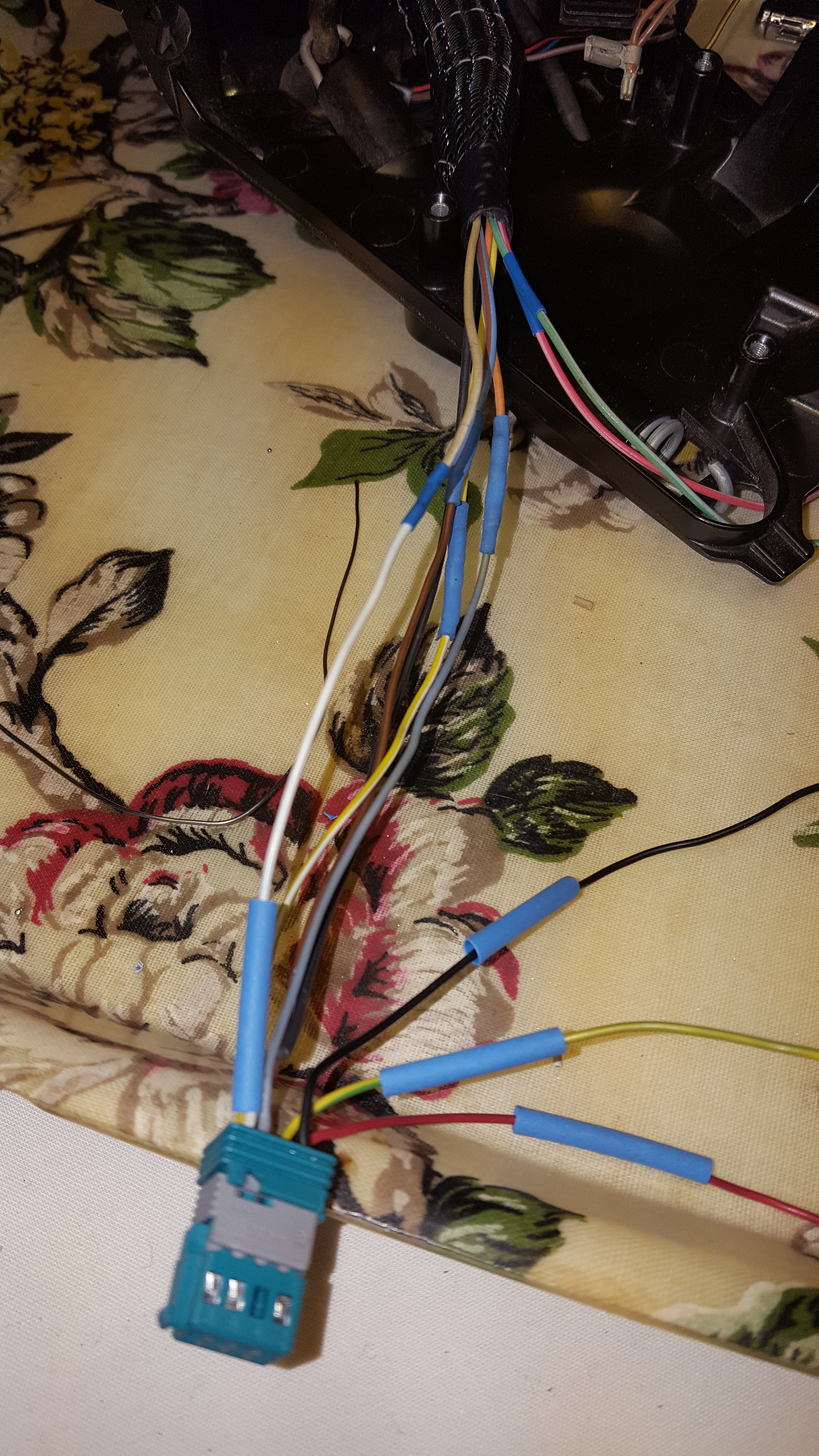
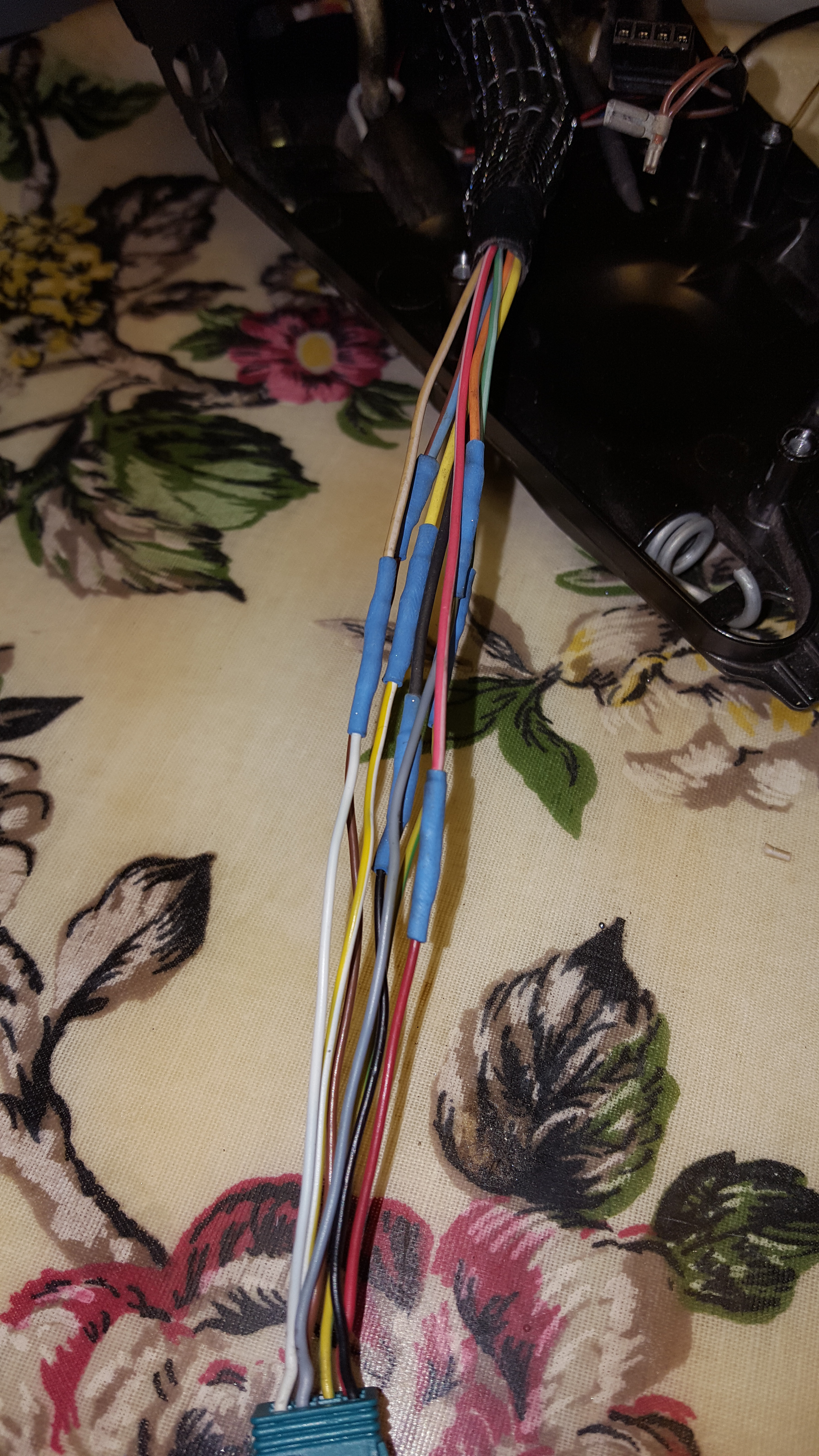
Once you've removed all the sticky fabric crap they wrap their looms in (it does serve a purpose other than to annoy you when removing it! it supports the wiring whilst allowing it to flex some unlike heat shrink, although it doesn't do a great job) you'll need to work out where to cut the wiring back to, if you can, it's best to stagger the joints, however, things like space restrictions, number of wires and position of the damage will restrict your options.
End of Part 1 (had to break it up because of the limit of 20 images per post )
)
Couple of points to note before I get started
My mirror frames and wiring are different per side as is standard, however I have a left hand drive n/s frame so that i can have the dimming function as well, and the frame I bought has the wiring for memory as well, your car will likely have different configurations between the two sides, but unlike mine, you'll have less wiring on the n/s not more!
- You'll need a fair bit of patience to do this and basic skills
- Tools required will be a soldering iron, wire working tools, small file or dremel type tool, small pieces of metal and something to shape them with, and likely a 5 point torx tool/set to remove the frame from the car.
- You will need some small lengths of wiring of a similar type/rating or heavier duty, don't go smaller, colour is not important so long as you note what goes to what!
- You'll also need some sort of cable wrap/heat-shrink or something similar, you'll get the idea from the pictures and as you look at it yourself.
- Some of the pictures might switch between left/right side as we go through, this is simply because i did both sides, and took pictures as i went, and used the best ones to show each stage.
Firstly, lets have a look at the problem....
- Your door mirrors have stopped:
- moving/adjusting
- defrosting
- folding
- Indicator failed (and not caused by the LED unit/Bulbs failing)
These are all indications of this problem, although of course it could also be the switch pack or other wiring issue, so first thing to do is remove the cover and have a look (this is done by folding the mirror in and using a flat blade screwdriver to release the cover clip and slide the cover off, you may need to push the mirror manually in at the hinge end to allow the cover to slide off, the process can be seen here
and
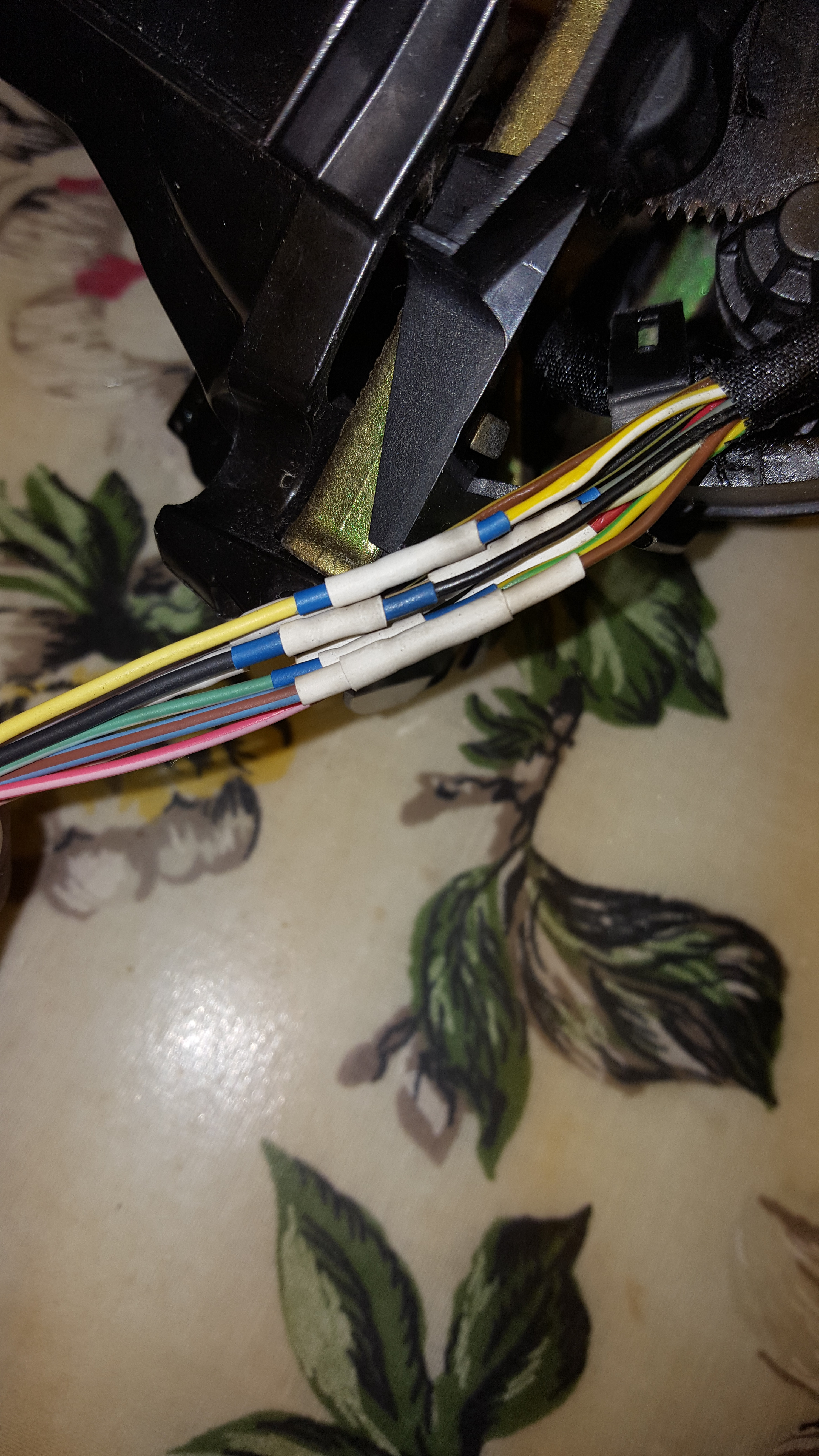
Now lets see if you are likely to have this problem, in the images you can see the problems highlighted.
Picture 1 - excessive bend is visible with damage to the wiring wrap, after you remove the mirror and unplug this loom you will notice it's really weak at this point, and hinges where cable breaks are

Pictures 2 through 4 - show the same bend that is the problem. (image 2 also shows the heating element wires, also crimped by bad placement when fitting the glass)
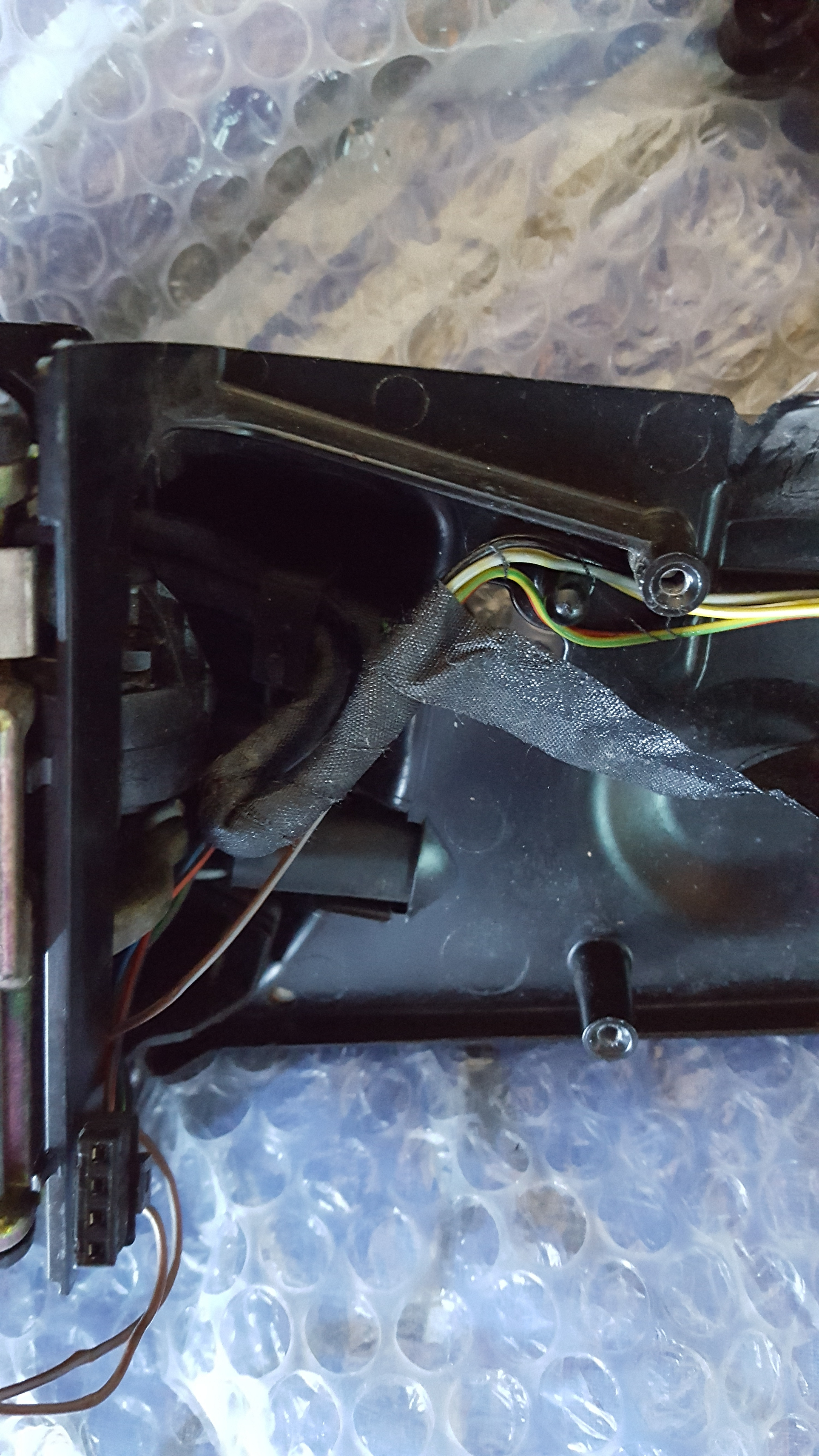
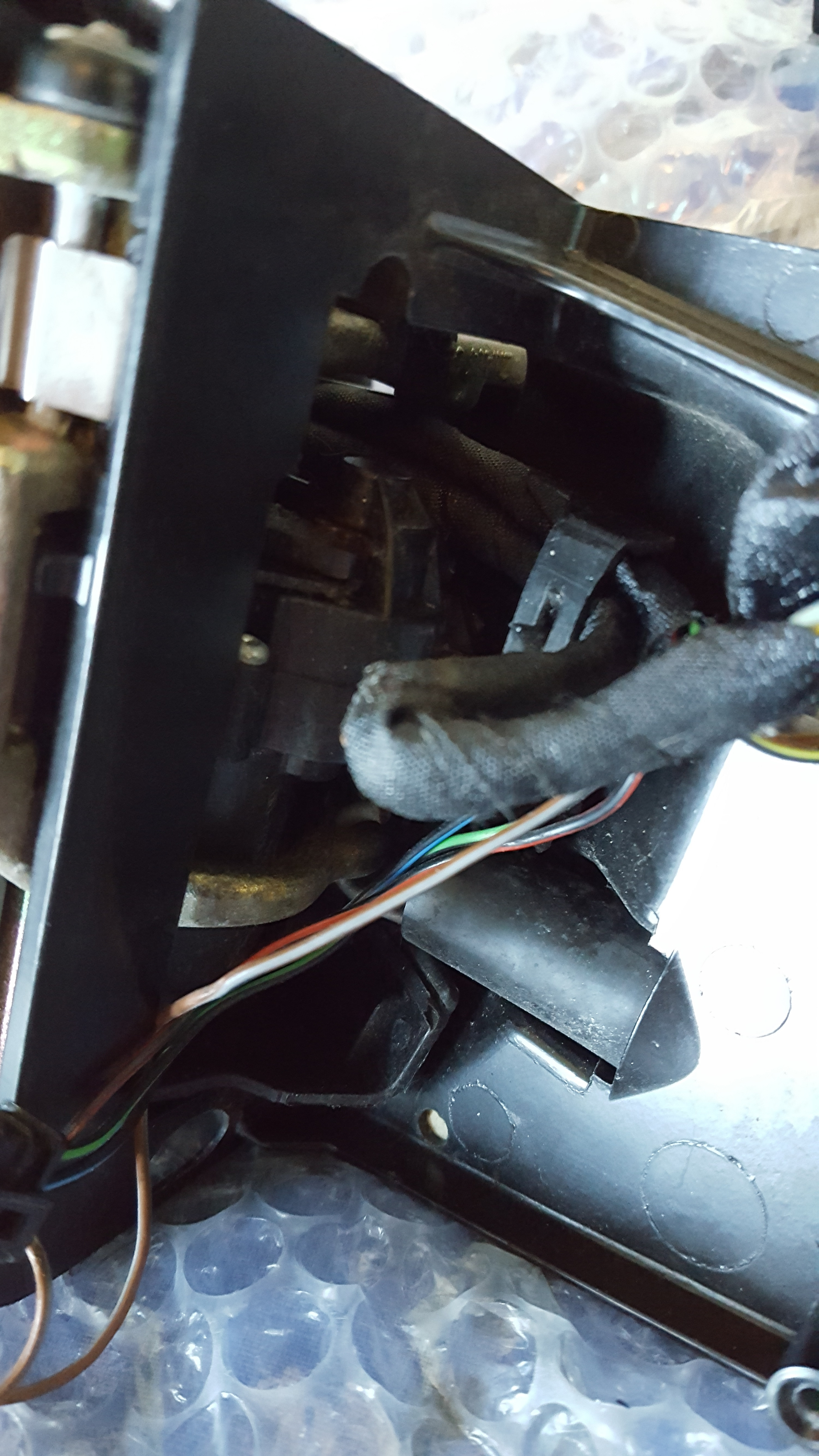
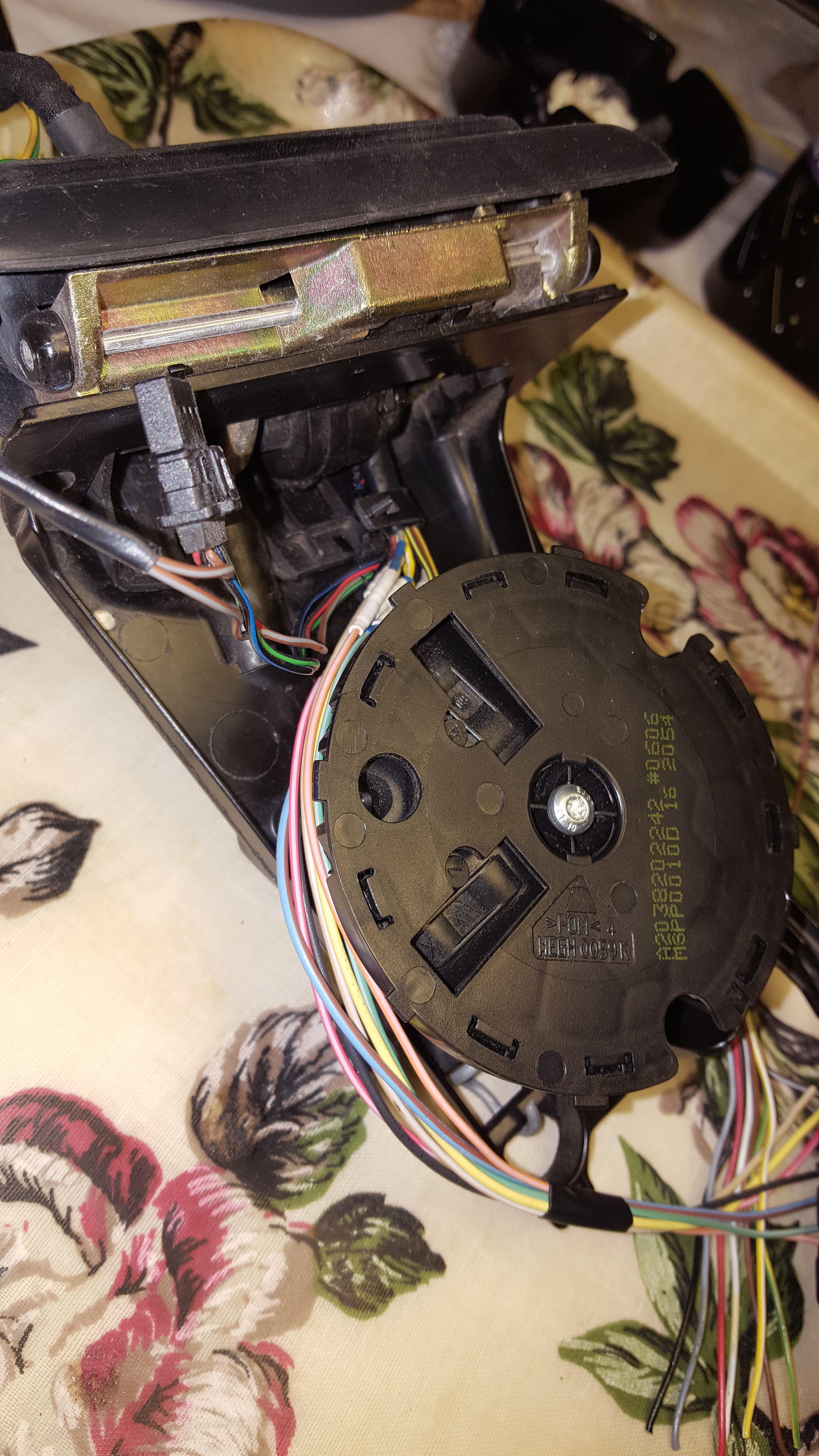
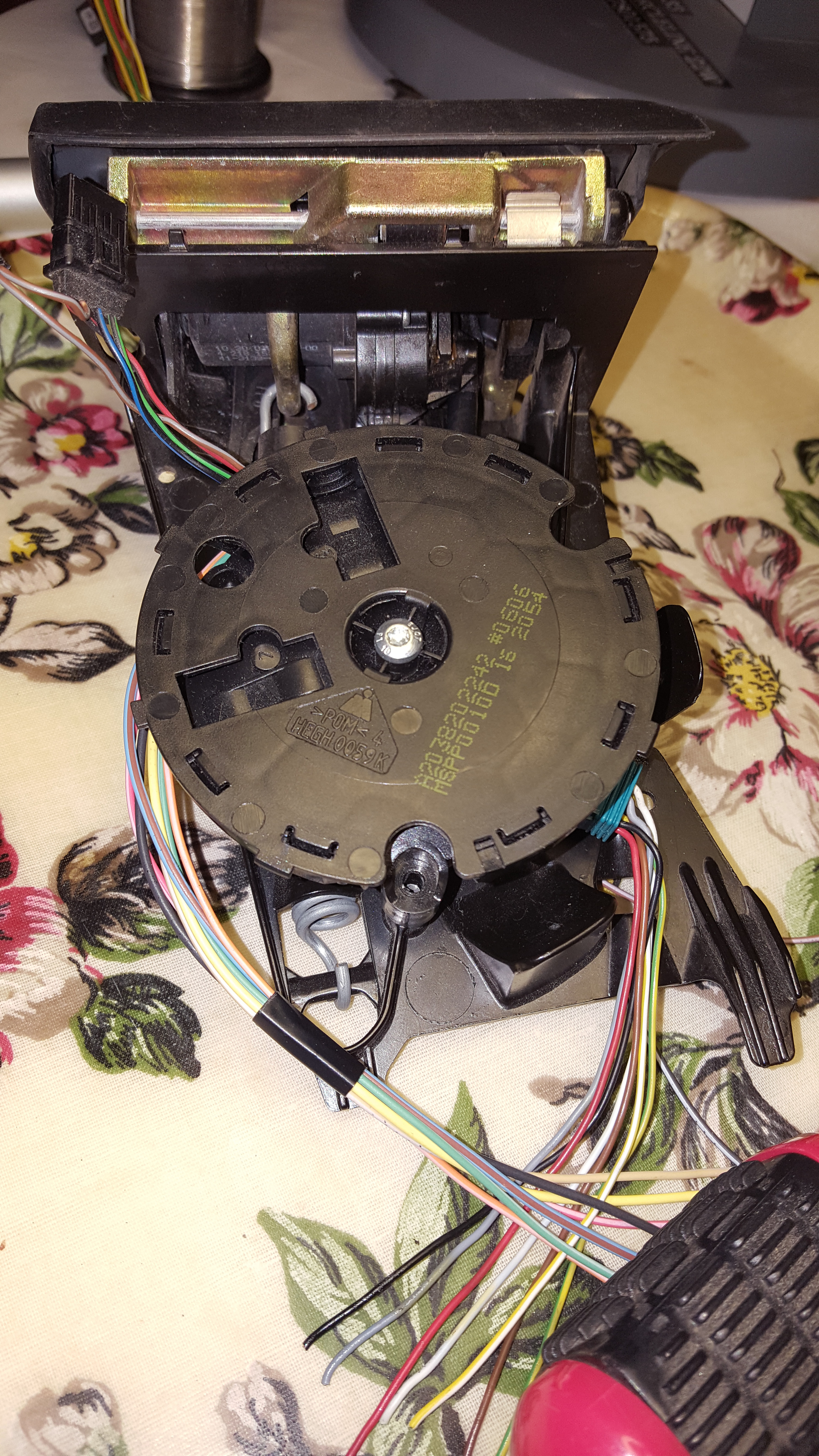
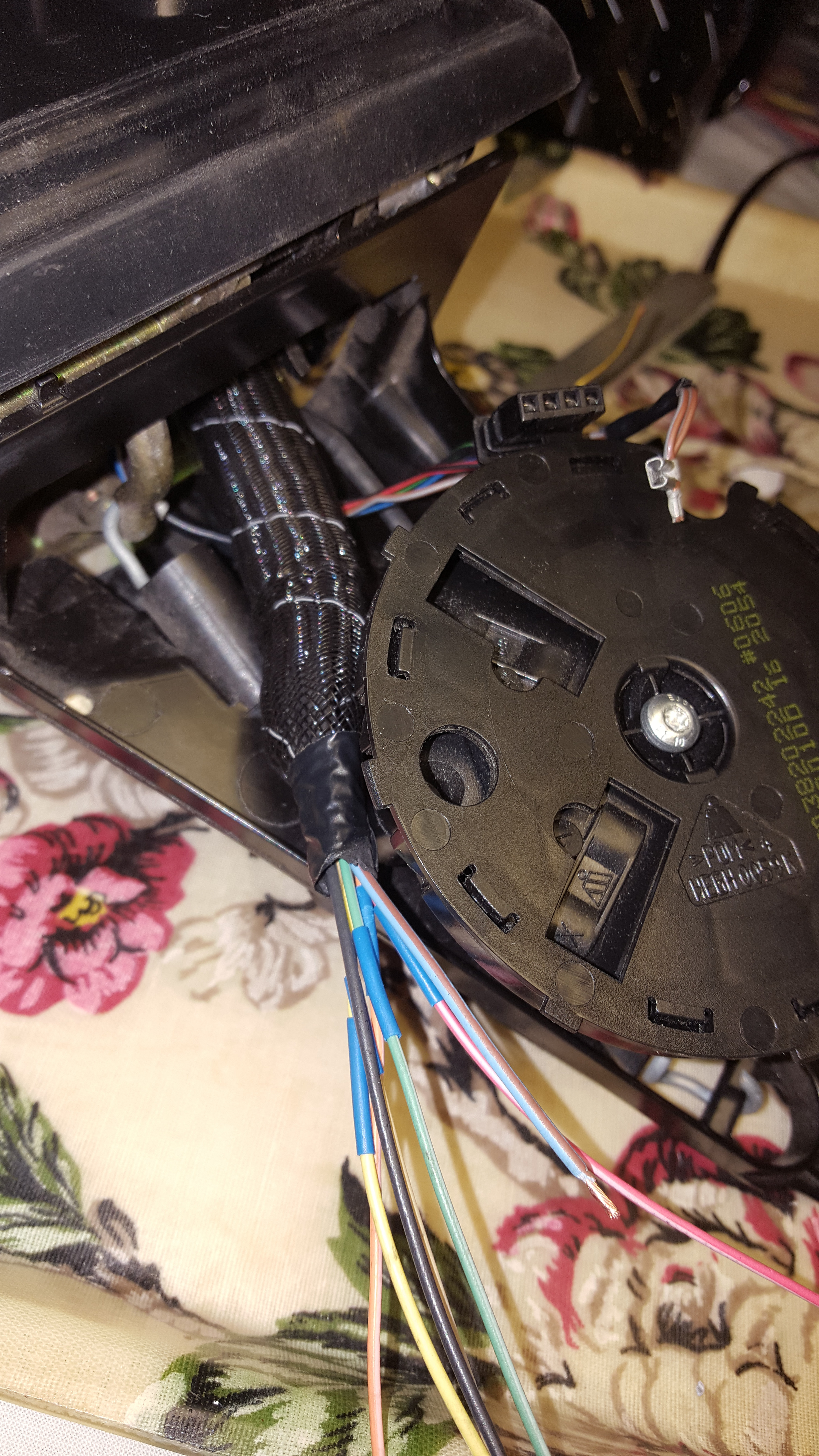
Pictures 5 through 8 - show the wiring with the mirror frame in various stages of folded, and you can see the toothed gear arm in close proximity to the loom
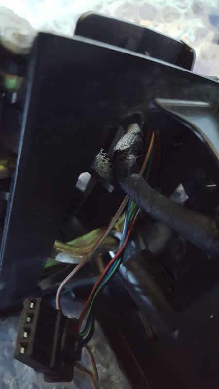


Pictures 9 and 10 - show what that toothed arm does to the loom wrapping

At this point if you are sure the problem lies in the frame wiring, you're going to want to remove the whole mirror unit from tthe car, it would be a lot harder to fix in situe, i'm not going to go into that process here, lots of videos on you tube for that if you can't work it out, beware of the likely need for a 5 point torx-plus drive bit to remove the frame from the car, unless you've had a helpful garage change it in the past and put regular allen key headed bolts in there when putting it back (PCS - thank you ollie)
So, once you have it off the car and start stripping it down, the problem becomes very obvious!
Pictures 11 + 12 - not so obvious in the image, but the cable may be broken at the arrowed points and when you hold it and flex it, it 'hinges' rather than bends in a loop

Picture 13.... ah the one that was literally sawed in half!! only thing holding that together i think was one wire and the fabric wrap!

Once you've removed all the sticky fabric crap they wrap their looms in (it does serve a purpose other than to annoy you when removing it! it supports the wiring whilst allowing it to flex some unlike heat shrink, although it doesn't do a great job) you'll need to work out where to cut the wiring back to, if you can, it's best to stagger the joints, however, things like space restrictions, number of wires and position of the damage will restrict your options.
End of Part 1 (had to break it up because of the limit of 20 images per post
)
Last edited by a moderator:


 it did surprise me how fast that happened though.