• The Forums are now open to new registrations, adverts are also being de-tuned.

Heater Wiring Diagram For CLK W208??

rallye_turtle

Member
Joined
Mar 5, 2008
Messages
34
Hi Guys,

Just wondering if anyone has got any knowledge of the wiring for the the heating system for a CLK W208. I've got this problem whereby the heater just blows out hot air, and when I turn the lights on the heater fan cuts out. Sometimes if I turn the lights on/off several times the fan sometimes comes back on and the lights come on too around the fan and vent knobs. I removed the heater controls and there is a large plug on the back attached to a loom, would anyone know where this loom goes to, Ie. does it go to a control unit. Please see photo below.
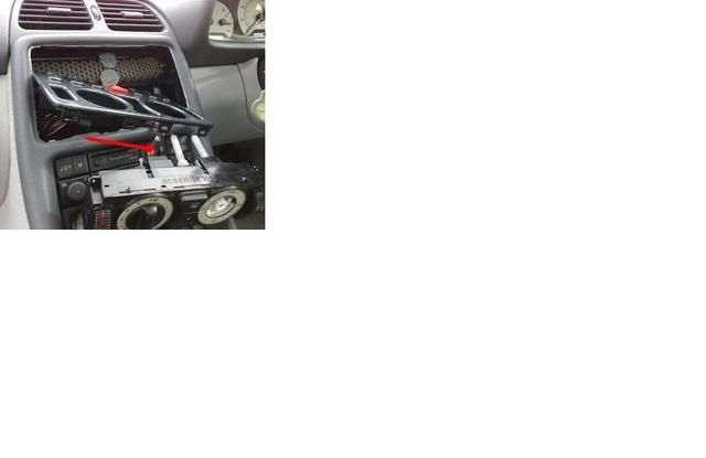
CentreConsole.jpg


Would anynne have a wiring diagram of this.

Any help would be much appreciated.

Cheers.
 
The wires from the pushbutton control module go almost everywhere.

The wiring is also dependent on the exact model year (manufacturing date), which AC option it has and if the car is a coupe or cabriolet.
 
The wires from the pushbutton control module go almost everywhere.

The wiring is also dependent on the exact model year (manufacturing date), which AC option it has and if the car is a coupe or cabriolet.


The car is '98, coupe and has AC thats as far as I know. Looking at the wires on the back they're pretty thin wires so I'm sure they would'nt be used for current supply but maybe just for control signals for a control unit which would then send out the current to the required devices such as the fan, duo valve etc. Thats my guess anyway.
 
The car is '98, coupe and has AC thats as far as I know. Looking at the wires on the back they're pretty thin wires so I'm sure they would'nt be used for current supply but maybe just for control signals for a control unit which would then send out the current to the required devices such as the fan, duo valve etc. Thats my guess anyway.

That isn't any guessing. The heater blower regulator would have ground, power and the control line from this pushbutton unit. Should be white/pink wire. Did you measure the duo-valve? This heater fan operation being dependent on lights sounds odd.
 
When the fan is working I tested the following with a voltmeter:

Duo Valve connector - 0 volts over all three contacts, I've heard if there is no voltage going to this connector then the duo valve is left in the open position (Hot), not sure if this is true.

Fan Regulator connector - There is a voltage reading which is below 5v and it varies as I alter the speed knob. However, when the fan stops working, there is no voltage going to this connector at all.

Could the above be caused by faulty relays, thats if the heating system uses any??

Swapped out the heater control panel today but still have the same issue. This is driving bonkers now.
 
I see you've already done a good deal of diagnostics. Did you measure the input voltage to the pushbutton unit?

The heater blower motor does not have any relay, just the regulator. These fail often but from your measurements it does not look like the regulator caused the issue, if there is no drive signal, the blower would not run.

Lights as such should not have any other connection in addition to the wiring from the IC for the illumination. But could it be corrosion at the driver side fuse and relay module?

You say you've tried with two different pusbutton units? Makes it likely that the fault is somewhere at the other end of the wires that leave the unit then :confused:
 
The 5 volts is correct when its there, the fan unit has 12volts on it

Is the fault a bad connection in the fuse box for the fan, they draw high current
 
Could possibly be a fault at the fuse box end. I think this weekend, I'm going to attempt to trace out the loom from the back of the heater control panel and see where it goes.

I've tried measuring the voltage on the multi plug that goes on the back of the control panel and as you can imagine was a bit of a pain as there are some 20 odd connectors on the plug, but if I can remember there were two connectors with a voltage reading, will re-check this on the wkend.

I'll be an expert on this heating system once this all gets sorted, lol!!

Cheers for the input guys.
 
If I'm on the right AC unit, it would have switched power at pin 21 (black/yellow wire), constant at pin 1 (red/yellow) and switched (15x, ignition key at position 2) at pin 22 (black/green).

PS. have you disabled private mails?
 
Will check these out. Hopefully it will be the same type of unit.

I should be able to receive mails mate.

Cheers
 
I should be able to receive mails mate.

Cheers

I cannot find the "send private message" option for you like it appears for others. I don't know if there is a post number limit but you've passed 20, that should be enough. :confused:
 
Looking breifly I see that the 12volt goes to the fan motor in on side and the ground side goes through the controller

The controller does have its own power source so not the blower fuse

The controller takes it from fuse f1 f38 this is shared with other things
 
Looking breifly I see that the 12volt goes to the fan motor in on side and the ground side goes through the controller

The ground should got to W1 ground point, behind the cluster (main ground point behind the instrument cluster). But this would be a common ground point for the heater blower motor and the pushbutton unit. Worth checking in my opinion.
 
some good suggestions here guys. What I'm going to do over the weekend is Tone the loom out so that I know exactly where it goes and then do a continuity check on the loom to see if there are any open connections.

Does the W1 ground point suffer from corrosion or any other issues??
 
Re the fan motor, one side goes stays at plus, the other side is grounded via the output from the conrol unit, and that completes the circuit.

As the lamp goes off in the control unit it is not the motor at fault , so at least one can forget that. the control live feed is shared with other things,, so in the fault state other things should not work that is the F1 and F38 this connector is fed from an unfused X box where the air con pump takes its power from.

Printing off circuits does not work well,, I will see if it will print the screen
 
Does the W1 ground point suffer from corrosion or any other issues??

I don't think so, a loose nut could be an option if it is built to use one. Corrosion should be more likely at the engine bay or trunk.
 
Re the fan motor, one side goes stays at plus, the other side is grounded via the output from the conrol unit, and that completes the circuit.

As the lamp goes off in the control unit it is not the motor at fault , so at least one can forget that. the control live feed is shared with other things,, so in the fault state other things should not work that is the F1 and F38 this connector is fed from an unfused X box where the air con pump takes its power from.

Printing off circuits does not work well,, I will see if it will print the screen


you mention F1 and F38 connector, what are these???
 
As Diesel Benz says yes they can.

I will try and print off something to help

Can you put up the first 6 VIN number please
 
Last edited:
As Diesel Benz says yes they can.

I will try and print off something to help

Can you put up the first 6 VIN number please


I'll have to dig that out over the wkend, but would appreciate it if you could find a print out to help.


Cheers

Wayne
 

Users who are viewing this thread

Back
Top Bottom