grober
MB Master
Here is a simplified version of how the throttle position linkage effects the throttle pressure acting against the governor pressure which is speed related. Under light acceleration a gear change would take place at a certain speed but under hard acceleration this change point is delayed till further up the rev range. All basically to do with the fact that in a hydraulically controlled box as speed increases hydraulic pressure increases and its how you modify /balance that increase in pressure to get the desired result in relation to road speed /engine speed /gear selected / accelerator position etc

Automatic Transmissions: Valves and Modulators - HowStuffWorks
this is a good nuts and bolts components " video of an autobox hardware.
[YOUTUBE]szu-0IqMygA[/YOUTUBE]
Automatic Transmissions: Valves and Modulators - HowStuffWorks
this is a good nuts and bolts components " video of an autobox hardware.
[YOUTUBE]szu-0IqMygA[/YOUTUBE]
Last edited:

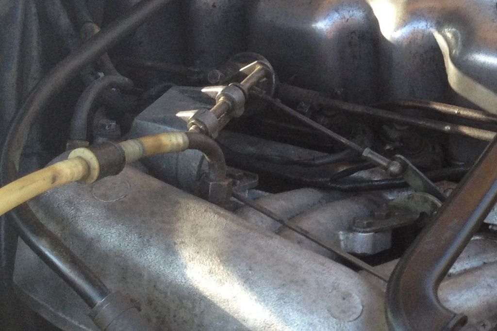
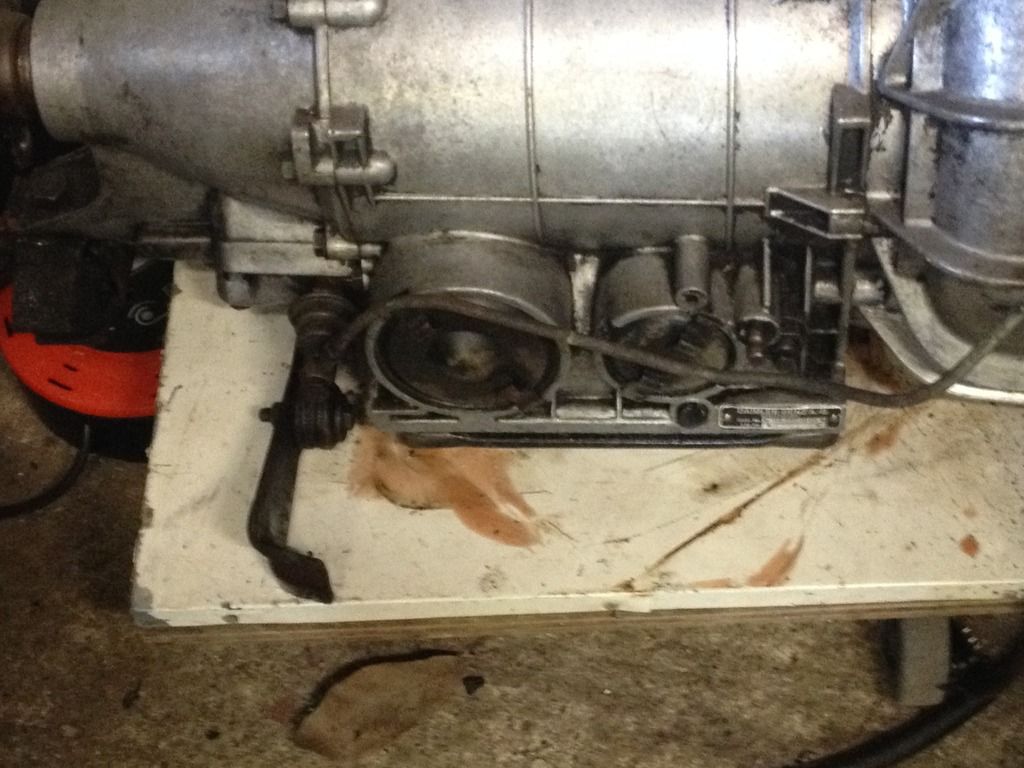

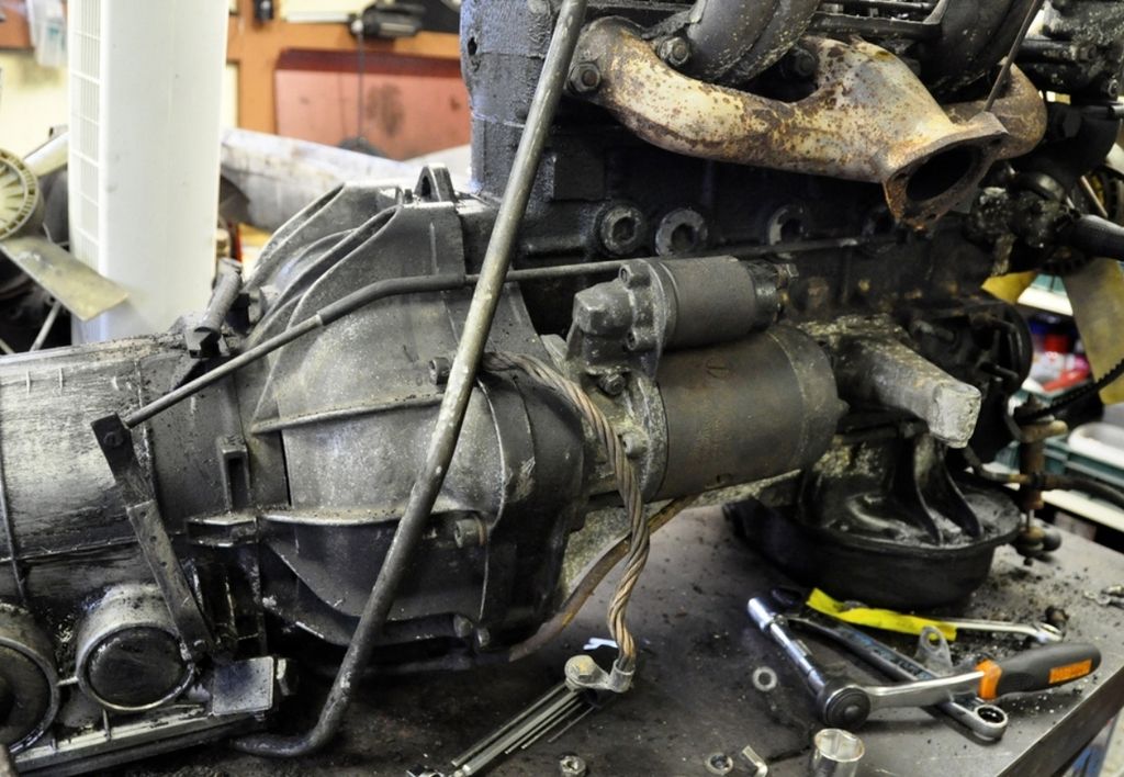
 Mercedes of that era seem to like mounting their throttle linkages on the inlet manifold or cam cover. I imagine its almost impossible to see down there without the engine out of the car?