• The Forums are now open to new registrations, adverts are also being de-tuned.

Rack and Pinion Conversion

Druk

Gone but not forgotten - RIP
Joined
May 28, 2004
Messages
5,300
Location
Not far from Edinburgh.
Car
2011 S212 E350CDi. 1981 R107 300TurboDiesel.
Hypothetically (at the mo) if Dave were to strip the old steering box system from a pre-90's Merc and replace it with a rack from a 2000 car can anyone foresee any problems or objections? :dk:


:D
 
Not for the annual test but technically the insurance company should be informed…would the car ever to be examined by the insurance company, would the examiner know that it should have a steering box rather than a steering rack, though? Quite unlikely, I would suggest.
 
The inner track rod ends have to have the same separation distance as the drop and drag links - other than that, providing the R&P is self-contained, the pumps are compatible, and the gearing suits the steering arms' lengths - no reason not to that I can see.
 
If you can basically mount the steering rack to emulate the position of the current recirculating ball system centre idler arm it should be fine. Any deviation from that line in a vertical or horizontal plane might increase the chances of unwanted bump steer effects or steering arms fouling bodywork with large suspension movement. To be honest there's probably a margin for error here but it might be difficult to predict what you might reasonably get away with.:dk:

edit:- Bellow said it before me. ;)
 
Thanks both. Kinda along the lines of what I was thinking.

A bit of research throws up this idea from the US which would seem to answer the bump-steer problem.


I had in mind a rack from a yr2000 E210. That is mounted behind the X-member so the rotation would be in the correct sense.
All I wonder is of the steering arm on a 210 is as long as the 107 ones? If not the steering lock angle at the road wheel would be compromised...as Bellow suggests.


.
 
Last edited:
It been done on several W201's and a few W124's also. Simon (Carat 3.6 and a bit :D) is the man to speak to.
 
Bellow and Graeme have covered it really, measure the distance between the inner track rod ends of the 107 and compare it the inner tie rod of the w210. You can use rack spacers to gain width but you cant narrow it.

There is a little flexibility in the height you mount the steering rack at, but try to keep it near the height of your original center drag link.

The amount of lock your road wheels have can be altered by varying the length of the steering arm. A shorter arm will give you more lock, a longer one gives you less.

For the w124 we use the lower part of the w210's steering column, I imagine the same would apply to the 107 but I've never tried it on one of those.
 
Last edited:
The amount of lock your road wheels have can be altered by varying the length of the steering arm. A shorter arm will give you more lock, a longer one gives you less.

Not forgetting that the angle of the arms viewed in plan dictates Ackerman effect - MB's set-up will be worth preserving.

Is there physically space enough for a rack? Its pretty bulky compared to the single drag link and that is the space it must occupy to maintain the correct geometry.

Two potential mounting positions? The obvious one - exactly where the drag link is. The other - higher and locating on the (retained) drop pivots above their mounting bushes.
 
Not forgetting that the angle of the arms viewed in plan dictates Ackerman effect - MB's set-up will be worth preserving.

Indeed. I've already done a fair bit of reading on this. Seems that I may already have inadvertently mucked with the Ackerman by fitting wider rims with a non-OE ET. This can affect the Ackerman angles on full lock; as witnessed by the squealing tyres on the varnished floor in the underground carpark at Monaco. :D:D It's an almost full-lock descent for 10 floors.

If I'm correct I have to replicate the angle formed by an imaginary line drawn from the C/L of the kingpin to the C/L of the diff.


Is there physically space enough for a rack? Its pretty bulky compared to the single drag link and that is the space it must occupy to maintain the correct geometry.

Plenty enough room. There's 6" between the engine X-member and the front of the bellhousing, 3 1/2" X-m to draglink, and the draglink is 2 1/2" below the sump although that decreases a lot when on lock and the Pitman and idler arms swing up. There's also the steering damper in there which can come out.
The other criteria I've learned is the inner track-rod joint pivot has to be on the plane of the top and bottom wishbone pivot points, the present set-up is out by 1/4" :crazy:. This lends itself to the rack being raised or lowered to suit since the pivots are at a big vertical angle. Since it's this that affects bump steer the fact that when on any lock at all this setting is destroyed and the possibility of bump steer introduced it makes a nonsense of getting it exact. One would have thought? ???????????


Two potential mounting positions? The obvious one - exactly where the drag link is. The other - higher and locating on the (retained) drop pivots above their mounting bushes.

Not sure what you mean by 'drop pivots' but the easiest is to replicate the set-up in the #7 pic and bolted through where the steering box comes out. There are mirror holes (bunged) in the N/S chassis for LHD cars :bannana:


.
 
Last edited:
Indeed. I've already done a fair bit of reading on this. Seems that I may already have inadvertently mucked with the Ackerman by fitting wider rims with a non-OE ET. This can affect the Ackerman angles on full lock; as witnessed by the squealing tyres on the varnished floor in the underground carpark at Monaco. :D:D It's an almost full-lock descent for 10 floors.

That will be the 'scrub radius' (I think the Germans refer to it as 'interference') gone for a burton. Nothing set in stone re scrub radii - until ABS entetrs the discussion. Chances are it was just the tyres realigning that could be heard.

If I'm correct I have to replicate the angle formed by an imaginary line drawn from the C/L of the kingpin to the C/L of the diff.

When viewed in plan, a line (drawn through the KPA (kingpin axis) at ground level, through the outer track rod end/steering arm continued to the car centre line. Usually it will coincide with the rear axle's centre, but not always (it can be ahead or behind).

170px-Ackermann_simple_design.svg.png


The other criteria I've learned is the inner track-rod joint pivot has to be on the plane of the top and bottom wishbone pivot points, the present set-up is out by 1/4" :crazy:. This lends itself to the rack being raised or lowered to suit since the pivots are at a big vertical angle. Since it's this that affects bump steer the fact that when on any lock at all this setting is destroyed and the possibility of bump steer introduced it makes a nonsense of getting it exact. One would have thought? ???????????
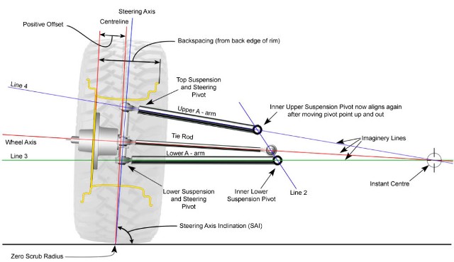
Accepting that wishbones have different lengths upper and lower, ideally the outer track rod is located in the plane of one of the wishbones and lies at the same angle as the wishbone in end elevation view. (The steering arm will also be at the height of either the upper or lower wishbones' outer pivots).
Variations on the theme are permitted the aim of the game being to have the arm in question mimic the arc of the wishbone it is closest to. (Consider a parallel double wishbone set-up (pure parallelogram) and see the freedom of TRE mounting. Now envisage an unequal length non-parallel wishbone system clearly the TRE position has to reflect the disparity of the two wishbones' motions.
Work from the end of the steering arm toward the steering gear as that sets the height. The TRE from there wants to be as close to parallel as possible to its nearest wishbone. If sited mid way between them then the TRE will be positioned on the vertical(ish) line drawn between the upper and lower wishbone pivots and at a height that is in proportion to its other end's positioning relative to the wishbones outer pivots.


Not sure what you mean by 'drop pivots' but the easiest is to replicate the set-up in the #7 pic and bolted through where the steering box comes out. There are mirror holes (bunged) in the N/S chassis for LHD cars :bannana:

On the other side (LH in your case) from the steering box there is a vertical tube from which the pseudo Pittman arm pivots. Currently you are considering attaching the rack below. You could use two (one each side) and operate via levers from the rack such that the rack is positioned higher and relay the motion to the lower height using the 'tubes' as pivots. Cumbersome though and better avoided.
 
That will be the 'scrub radius' (I think the Germans refer to it as 'interference') gone for a burton. Nothing set in stone re scrub radii - until ABS entetrs the discussion. Chances are it was just the tyres realigning that could be heard.

There's certainly no undue or uneven wear on the front tyres so whatever the cause it's discounted.


When viewed in plan, a line (drawn through the KPA (kingpin axis) at ground level, through the outer track rod end/steering arm continued to the car centre line. Usually it will coincide with the rear axle's centre, but not always (it can be ahead or behind).

170px-Ackermann_simple_design.svg.png


.

'but not always (it can be ahead or behind)'.

I wonder what the circumstances would be to have either of those occur?
I stretched a string across the thing today and it's not far away on the current set-up...but not perfect. The steering arms on a 107 are about 9" long and I can see them being re-manufactured if it all comes about.


On the other side (LH in your case) from the steering box there is a vertical tube from which the pseudo Pittman arm pivots. Currently you are considering attaching the rack below. You could use two (one each side) and operate via levers from the rack such that the rack is positioned higher and relay the motion to the lower height using the 'tubes' as pivots. Cumbersome though and better avoided.

I'm with you. The 'idler' arm on the N/S is through a weld-on so I'm thinking it might stay but be made redundant just in case, but mount a rack on a subframe. Easier to strip out if it all doesn't work.


.
 
'but not always (it can be ahead or behind)'.

By design...

I wonder what the circumstances would be to have either of those occur?

....when anti-Ackermann geometry is sought. Colin Chapman's belief was that the lighter loaded inner wheel should never be asked to run at a higher slip angle than the outer - which is in essence what Ackermann geometry does, so some cars are designed with reduced - relative to what Ackermann geometry would impose - lock on the inner wheel.

I stretched a string across the thing today and it's not far away on the current set-up...but not perfect. The steering arms on a 107 are about 9" long and I can see them being re-manufactured if it all comes about.

If you get the opportunity to compare steering ratios rack vs recirc'ball ie lateral motion (at the TREs) vs steering wheel angle then it should become apparent if the steering arms need to be altered. Otherwise, they are best retained as they are, where they are.

I'm with you. The 'idler' arm on the N/S is through a weld-on so I'm thinking it might stay but be made redundant just in case, but mount a rack on a subframe. Easier to strip out if it all doesn't work.
.

Relief! That was one clumsy description from me and a more elegant one is still not forthcoming!
 
Accepting that wishbones have different lengths upper and lower, ideally the outer track rod is located in the plane of one of the wishbones and lies at the same angle as the wishbone in end elevation view. (The steering arm will also be at the height of either the upper or lower wishbones' outer pivots).
Variations on the theme are permitted the aim of the game being to have the arm in question mimic the arc of the wishbone it is closest to. (Consider a parallel double wishbone set-up (pure parallelogram) and see the freedom of TRE mounting. Now envisage an unequal length non-parallel wishbone system clearly the TRE position has to reflect the disparity of the two wishbones' motions.
Work from the end of the steering arm toward the steering gear as that sets the height. The TRE from there wants to be as close to parallel as possible to its nearest wishbone. If sited mid way between them then the TRE will be positioned on the vertical(ish) line drawn between the upper and lower wishbone pivots and at a height that is in proportion to its other end's positioning relative to the wishbones outer pivots.

The above can be simplified by considering the instantaneous pivot point.
Viewed in end elevation draw a line through the lower wishbone pivots (inner and outer) and extend it beyond the centre of the car. Repeat for the upper wishbone and where the lines converge is the instantaneous pivot point of the suspension assembly - crucially it defines the arc the hub/upright transcribes during suspension travel (bump/droop and roll). As the end of the steering arm's motion is defined by that motion than it becomes obvious where the inner TRE needs to be located to avoid pulling or pushing the arm into a steering motion during suspension travel.
NB, parallel wishbones have no convergence and the convergence point (for unequal w'bone set-ups) moves with suspension travel - it is not fixed. It will be consistent however for the position that equates to ride height and a little either side (up or down) from it.
Viewed from that perspective the positioning of the TRE becomes obvious.

Bellow old chap :D. Up till now I've been fine but I'm afraid this is way over my wee heid . D'you fancy a day out in Bathgate and you can show me what you mean? Otherwise I'm afraid...it's wooooosh. Good of you to give it a try though :thumb:

Derek.
 
I see some Druk magic happening to his SL.
 
A picture being worth 1000 words...

2934_9mg.jpg


Ignore the line running through R and instead view the arc the wheel/hub/etc assembly transcribes pivoting around point A. It is that arc that the track rod pivoting at its inner and moving vertically at its outer has to emulate. Were it possible the ends of the rack would ideally be placed at point A but that is clearly impractical thus some compromise is required.
 
Viewed from the perspective of wishbone arcs.

728217d1368566966-new-product-928-bump-steer-kits-bumpsteer_diagram.jpg


Viewed from the perspective of instantaneous centres. Note that the TRE is located on a line drawn between upper and lower wishbone inner pivots and how the height is defined by the steering arm height.

bump-steer-pro-touring1.jpg


As above with numbers.

2422-new_2009-03-13-bumpsteer2.jpg
 
xxx
 
Last edited:

Users who are viewing this thread

Back
Top Bottom