• The Forums are now open to new registrations, adverts are also being de-tuned.

Mercedes W114 250 Coupe - help!

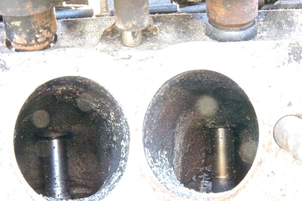
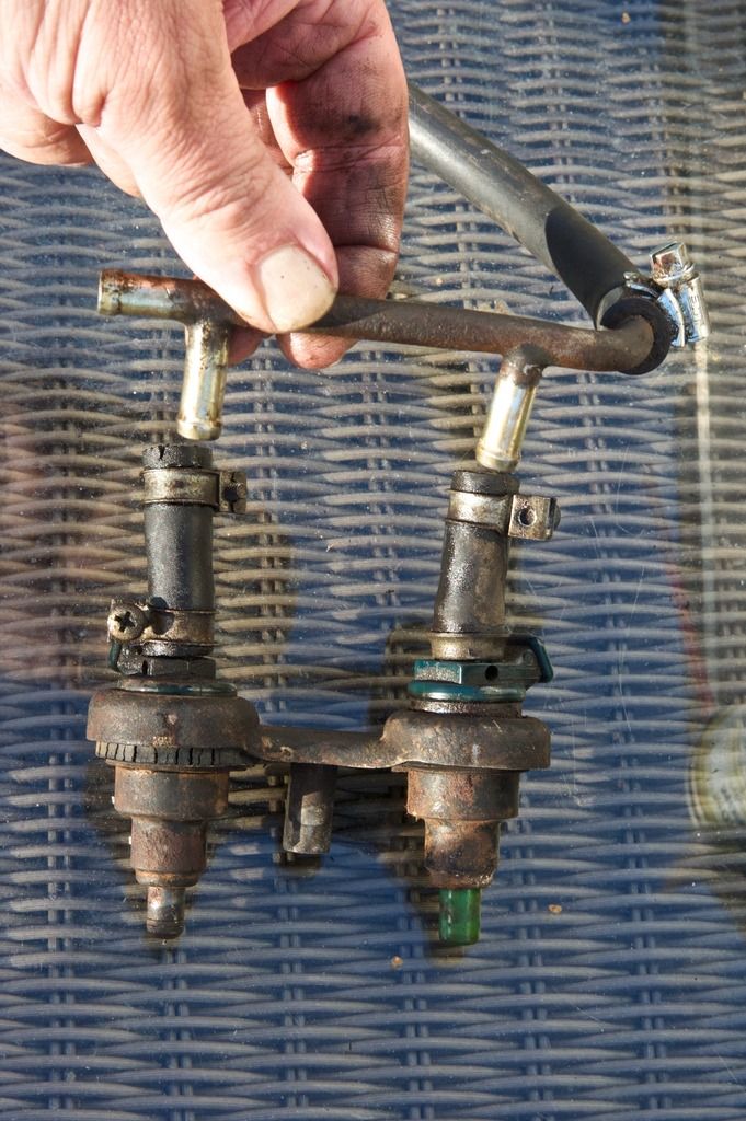
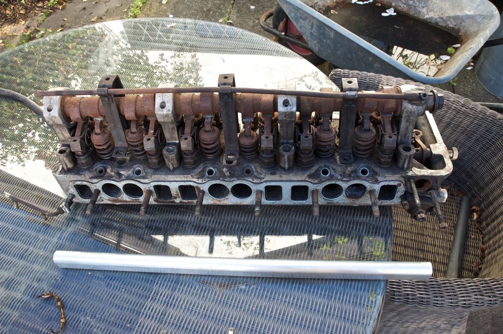
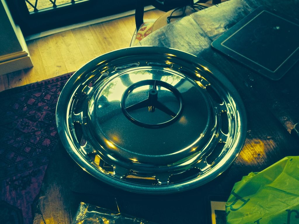
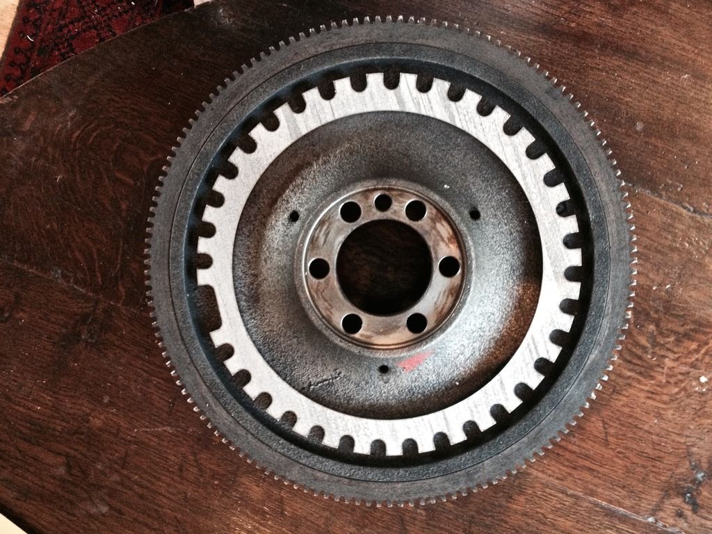
Ahem. If it works I take no credit for the job other than I know the man who did it. The same man who did these little beauties.


Sometimes it's not what you know...

Of course if it doesn't work I know exactly who to blame. :devil:


.


wow thats some impressive work, assuming your man is a dab hand at cc and milling?

I am just utilising one of my cnc contacts for some custom hub parts,

will keep an eye on this build
 
Another test card

1967-Mercedes-Benz-250SL-Rear.jpg


1967-Mercedes-Benz-250SL-Front-940x636.jpg
 
Returning to flywheels and sensor location, I have just had an hour of my life wasted which I shall never get back.

Planning to fit the trigger wheel on the back of the flywheel I'd thought I'd ask Mr Trigger wheel.com for the dimensions of the wheel that should fit and the one bit I need, namely the depth of the teeth (so I can consider sensor mounting point).

First reply - get one bit of info back, but not the teeth depth.

So I ask for the teeth depth again.

Second reply - get asked what I'm planning so he can help me decide, wants photos etc. But no teeth depth.

So I write out in full what I am doing and why I need the teeth dimensions. This was against my better judgment as this is a simple request that ought not to need chapter and verse.

Third reply - he says that should work. No teeth dimension given.

Ask one final time.

No reply to date. Anybody involved in customer facing jobs here - don't make buying stuff like pulling teeth.

Now looking for alternative suppliers. Grrrrr....
 
Last edited:
''Why do adults always ask number questions'' asked The Little Prince.

They do - and Mr Trigger should be in a position to answer them. Take Mr Trigger outside and shoot him. If it's raining - inside is fine...
 
He's finally got back to me. 8 to 9 mm.

In the meantime I found a US supplier that had a 1/4 inch depth - 6.35mm, which if replicated on the flywheel edge might make drilling it a real possibility.

Anyway, decided to crack on with all specs as I need to re-kindle some interest and momentum from me.
 
there's this article
View topic - How to make an ignition trigger wheel
Which implies the ideal tooth width is the same as the end of the sensor width and the gap greater than the sensor width to avoid the sensor seeing two teeth at the same time. It makes no specific recommendation as to a minimum tooth depth save to say it depends on sensor specification. This might be determined by examination of the toothed wheel dimensions in an existing vehicle application of the sensor? E.g. If its a Ford sensor- what's the tooth dimensions of the timing wheel on the car? That said from examination of various toothed wheels the depth should be equal or greater than the tooth width as a rough rule of thumb. The effectiveness of this dimension might also be dependent on sensor proximity. Greater tooth depth might permit greater latitude for clearance for example. Will try to find out more.

ps remember this
http://www.sbdev.co.uk/Info_sheets/Crank_Sensors/36-1 Trigger wheel Setup Drawing-pdf.pdf

it is recommended that the depth of the cut out between each tooth is as deep as possible. The reason for this is the deeper the gap the harder it will be for the sensor to detect anything other than the tooth. This is particularly important if your engine or equipment fitted to the engine produces interferance, this will help to reduce the problem of signal degradation
 
Last edited:
Paint template for the wheel trims arrived today, which is good timing. Fits the centre star perfectly. Photo highlights how bad an iPhone 4S camera is in low light though...

w114painttemplate_zpsncsbecu4.jpg
 
No No No!
 
Trigger wheel arrived back end of last week but horribly busy over the weekend. I think this fits rather nicely. The wheel itself sits about a mm below the lip of the flywheel, so plenty of clearance.

w114trigger_zpsaffxtd3l.jpg
 
Last edited:
LOOKS A SOLID PIECE OF KIT :thumb: --- Standard issue[ part no?] or one off special? Might be useful for anyone else contemplating such a conversion following the thread?
 
So the sensor is going to be mounted longitudinally on the engine back-plate 'looking' aft? Do you have a spot in mind?
 
Yes - there is an inspection plate that is bolted in at the base of the back plate - we are going to strengthen it to rock solid and then it will be a really good mounting point without the need to attach the sensor to the sump underside. Fabricating a bracket with adjustment will be the fun bit.

Standard issue Graeme - one of the larger ones available certainly, but the large centre hole seats it firmly on the flat part of the flywheel back. Trigger wheel attachment mechanism to be decided but the aim is to have an absolutely rock solid signal.
 
Next job is to measure up the fuel rail, the aluminium rail for which also arrived at the same time.
 
The inspection plate from earlier photo (right hand side). Without it life would be very difficult indeed!

housing2_zpsibcmyqe4.jpg
 
So sun out shining bright and with half an hour before having to cook an early dinner (choir tonight) I dug out the old fuel rail, spare cylinder head and newly arrived fuel rail to start thinking about how to make the new one work.

The head with fuel rail in place. Three pairs of two injectors, the individual pair distance less than that between each pair. Each pair held in place on the head by a metal bracket that holds the injector and fits into a bolt (stud?) built into the head. Fuel pressure regulator 2/3rds the way along (I'm assuming fuel is coming from the front and the regulator is supplementing flow for the last pair of injectors).

w114fuelrail%201_zpsuefhblsa.jpg


w114fuelrail2_zpseyhfjphs.jpg


w114fuelrail4.5_zpsipfp2xg5.jpg


When mounted the injector fires into a pre-chamber and the nozzle is not visible (you can just about see the injector hole in the top right of each inlet.

w114fuelrail5_zps7wi3qtax.jpg


The pairs of injector are fed by a rubber hose from the rail.

w114fuelrail3_zps01uzhbxu.jpg


Each injector is held in by a cir clip and a grommet/O ring.

w114fuelrail6_zpsoowgpnle.jpg


The replacement rail (if I use it) is a solid billet of aluminium drilled with a wider hole than the old pipe.

w114fuelrail8_zpsdrfhqhmf.jpg


w114fuelrail7_zpsugtwzqtv.jpg
 
Last edited:

Users who are viewing this thread

Back
Top Bottom