• The Forums are now open to new registrations, adverts are also being de-tuned.

Mercedes W114 250 Coupe - help!

Precision will be everything re drilling the fuel rail. I await the plan. I have an idea as to how to do it also, but after you sir...
 
I might be a little while...

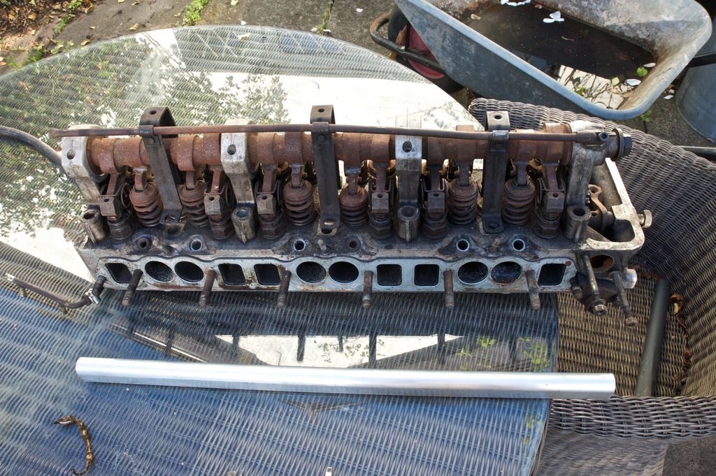
My plan worked on the bare cylinder head without manifold or cam cover, but it's appreciably tighter on the complete engine, hence the usefulness of that. The good thing is the rail is beautifully sandwiched tween alloy manifold and cover, so the rather thuggish rail blends in much better.

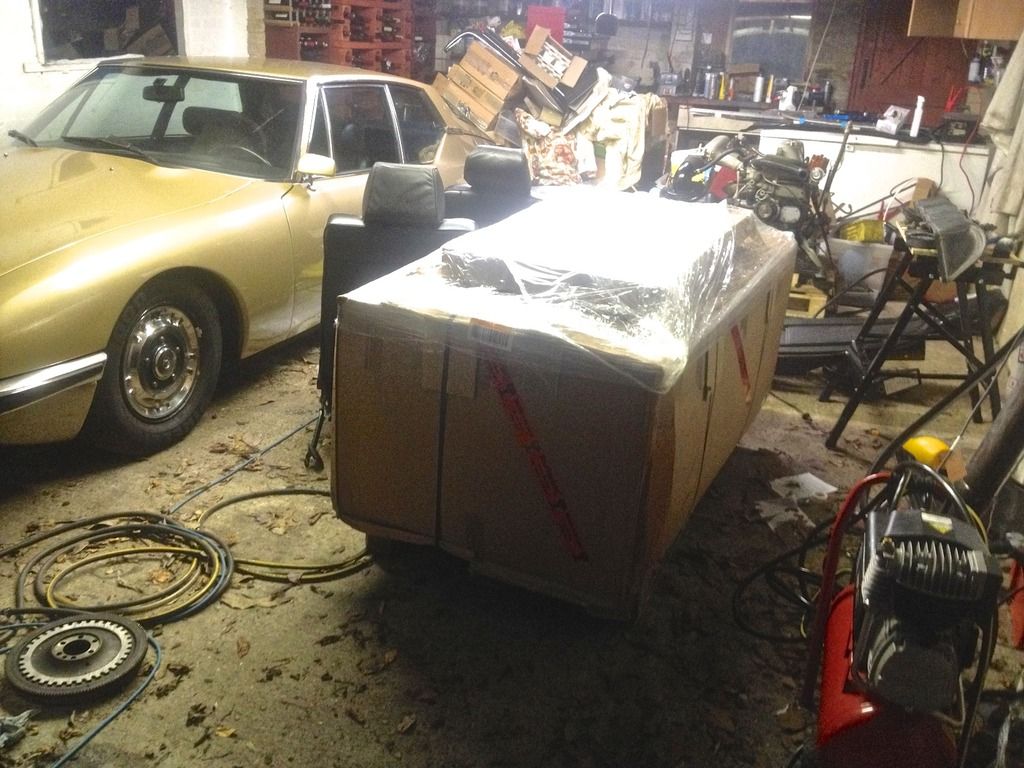
However, seats and carpets have arrived! Ever efficient UK delivery driver had a tail-lift and one of those handtruck things, and he said delivery was normally timed later for privates as they were more likely to be in. Truck was a bit smaller too.

And here they are in all their glory!

seatdelivery_zpspbtwinzi.jpg
 
Their glory box more like.
 
A hint at the contents.
 

Attachments

  • seatdetail.jpg
    seatdetail.jpg
    229.5 KB · Views: 32
  • seatsandcarpet.jpg
    seatsandcarpet.jpg
    249 KB · Views: 35
I did find that thread quite funny, particularly the early attempt at a fuel rail out of copper piping. I am seeing a friend tomorrow whose wife, a leading viola player, has retrained as a plumber, and I'll ask if she can knock me up one that will cope with petrol at 3 bar pressure. Oddly I expect her answer will be negative! However, his fuel economy gain is pretty impressive.

I need to take a lot of measurements and photos to show how the fuel rail can fit and be secured. I posted a few months ago on the current fuel rail set up, which is worth repeating because it gives some pointers to constraints and possible solutions.

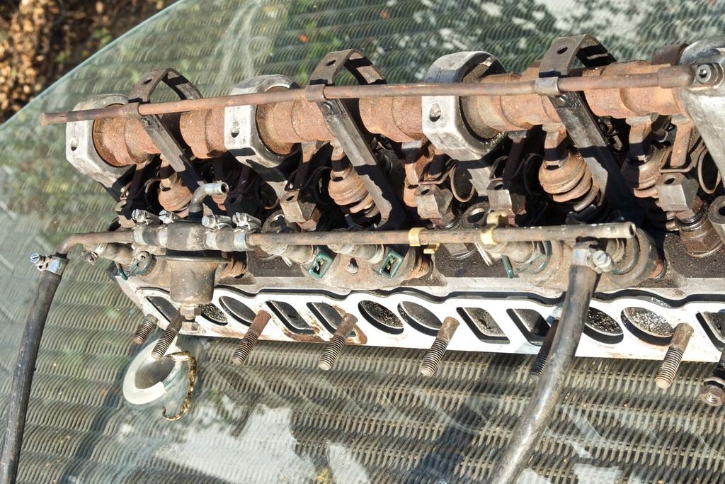
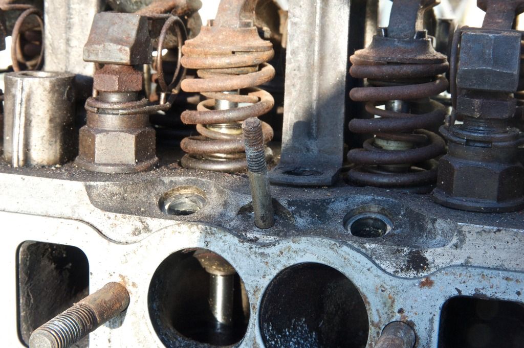
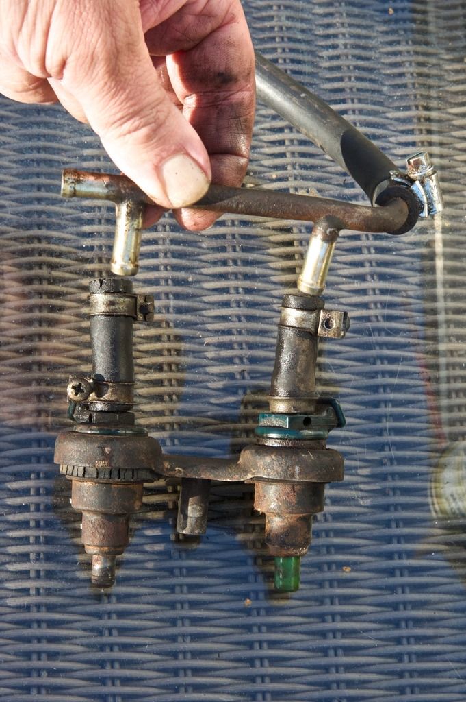
The head with fuel rail in place. Three pairs of two injectors, the individual pair distance less than that between each pair. Each pair held in place on the head by a metal bracket that holds the injector and fits into a bolt (stud?) built into the head. Fuel pressure regulator 2/3rds the way along (I'm assuming fuel is coming from the front and the regulator is supplementing flow for the last pair of injectors).

w114fuelrail%201_zpsuefhblsa.jpg


w114fuelrail2_zpseyhfjphs.jpg


w114fuelrail4.5_zpsipfp2xg5.jpg


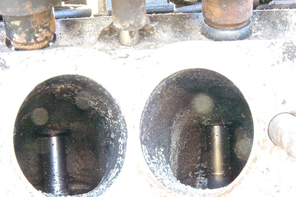
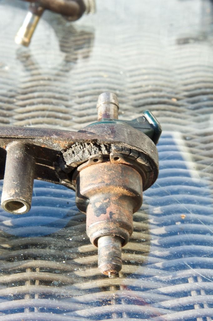
When mounted the injector fires into a pre-chamber and the nozzle is not visible (you can just about see the injector hole in the top right of each inlet.

w114fuelrail5_zps7wi3qtax.jpg


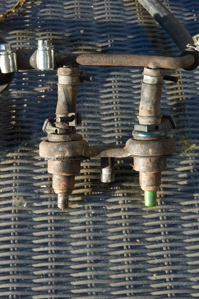
The pairs of injector are fed by a rubber hose from the rail.

w114fuelrail3_zps01uzhbxu.jpg


Each injector is held in by a cir clip and a grommet/O ring.

w114fuelrail6_zpsoowgpnle.jpg


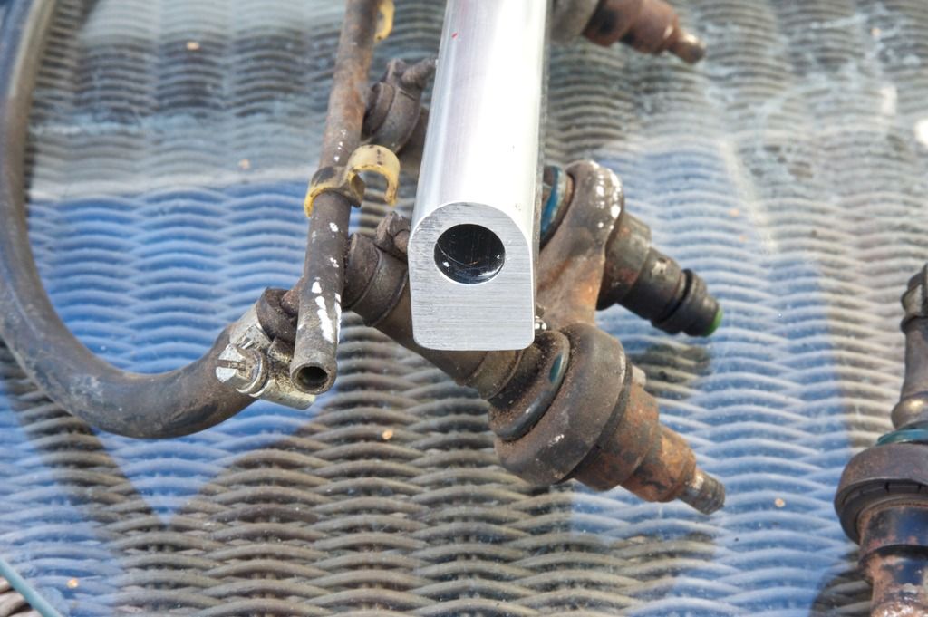
The replacement rail (if I use it) is a solid billet of aluminium drilled with a wider hole than the old pipe.

w114fuelrail8_zpsdrfhqhmf.jpg


w114fuelrail7_zpsugtwzqtv.jpg
 
Last edited:
Fuel rail supply is from both ends and return is via the pressure regulator. Restricting the return [ adjusted via the bolt/locking nut] is how the rail pressure is regulated. There will possibly also be a take off for an additional cold start valve.
The advantage of flexible injector coupling pipes and mounted via grommets means the injectors have a degree of movement to possibly help line up with the injector ports.
Electrically I believe the orginal D Jet injectors were fired in two blocks of 3 rather than individually??
 
What I like about the existing injector pair holders is their rigidity - they absolutely lock the injector into the holder and the holder into the head. I have sourced the grommets and the circlips, plus replacement rubber bungs, so would like to use these to hold in the injectors as before (they fit the new ones).

I think, with extensions, it should be possible for the three bolts in the head that lock the injector holders in place also to hold the fuel rail in place - via a hollow tube tapped into the rail billet (but not into the fuel line). That would solve locking it into place.

I think locating the injectors into holes drilled in the rail is going to lead to it being very tight for space, so was toying with these weld on bosses to the main fuel rail. Given the weight of the replacement fuel rail I'd be much less comfortable with it being the same height above the head as the existing rail and don't like the rubber hoses as they could be much more inclined to flex with more weight above.

dsc_0182-crop-b.jpg


Thought to be given to connectors at either end of the rail and the positioning of fuel pressure regulator. Also, fuel pump choice and location (one pump or two?).
 
Last edited:
Fuel rail supply is from both ends and return is via the pressure regulator. Restricting the return [ adjusted via the bolt/locking nut] is how the rail pressure is regulated. There will possibly also be a take off for an additional cold start valve.
The advantage of flexible injector coupling pipes and mounted via grommets means the injectors have a degree of movement to possibly help line up with the injector ports.
Electrically I believe the orginal D Jet injectors were fired in two blocks of 3 rather than individually??

I'm not disputing that both ends of the rail are supplied but modern practice is to supply only one end and have that supply and the volume of the rail sufficient;y large so as to ensure equal pressure is available to all injectors. The 'banks of three' theory though may make supplying both ends prudent - if not an added complication,

What I like about the existing injector pair holders is their rigidity - they absolutely lock the injector into the holder and the holder into the head. I have sourced the grommets and the circlips, plus replacement rubber bungs, so would like to use these to hold in the injectors as before (they fit the new ones).

I think, with extensions, it should be possible for the three bolts in the head that lock the injector holders in place also to hold the fuel rail in place - via a hollow tube tapped into the rail billet (but not into the fuel line). That would solve locking it into place.

I think locating the injectors into holes drilled in the rail is going to lead to it being very tight for space, so was toying with these weld on bosses to the main fuel rail. Given the weight of the replacement fuel rail I'd be much less comfortable with it being the same height above the head as the existing rail and don't like the rubber hoses as they could be much more inclined to flex with more weight above.

dsc_0182-crop-b.jpg


Thought to be given to connectors at either end of the rail and the positioning of fuel pressure regulator. Also, fuel pump choice and location (one pump or two?).

If the rail will take the welding with zero distortion (your welder should advise) then all looks good but I wouldn't go crazy with multiple rigid mountings as the rail being aluminium may want to expand with heat. To that end a small amount of lengthwise flexibility would be wise.
Beware vibration. The six should be smooth, but the further the rail from the head the worse will any lateral vibration be felt. Aluminium's natural tendency is to work harden which in the extreme can lead to cracking. I;d avoid tapping unless using an intermediate mounting with some elasticity (feasible, motorcycles are festooned with such).
Were it aesthetically acceptable, I would secure the injectors to the head with the existing studs (yes, they are studs), press snugly the rail directly to the injectors via the welded bosses then tywrap the rail at say, three equidistant points to brackets mounted on the injector retaining studs or some other appropriate pick up points. On any other car with no regard to aesthetics merely functionality, that's what I'd look to do. I'd do my best to arrange the (stout) tywraps to not look like tywraps though (not difficult - just hide the ratchety bits). I'm not saying that is how you should do yours, merely throwing some ideas in.
The main force to be considered is that of the fuel pressure trying to push the rail off the injectors. Anything that 'pulls' it hard down on the injectors while giving a touch of freedom to expand and avoiding localised stress points from vibration is what I'm trying (clumsily) to advocate.
 
Much food for thought there Bellow, thank you.
 
Thought to be given to connectors at either end of the rail and the positioning of fuel pressure regulator. Also, fuel pump choice and location (one pump or two?).

If the rail has sufficient volume (twice the original's? - easily measured) then feed one end and if the mounting is all good and the regulator not to heavy - mount the regulator on the other end?

Fuel pump(s) best mounted as close to the tank as possible (pressured line prevents vapour locks). I'd aim for one pump (if it fails the engine dies rather than being killed by seizure as could happen if one of a pair failed and went unnoticed).
Presumably there is a calculation based on injector flow plus some headroom on top. Ultimately it can be related to HP.
 
The existing set up has the pump very close to the tank - the original is in need of replacement and I'll probably use one from a later car with similar rail pressure and output. There is a swirl pot in between then simply fuel line to rail.

If the fuel pressure regulator is mounted at the end at the start of the return pipe, would a simple line in line out one suffice? I see three and even four line ones (with connection to manifold) but not sure if they are necessary.
 
Watch for clearance for the electrical connectors if the loom forces specific orientation and the bosses will have to be welded bang on the spacing of the injectors as with the intended set up there will be no compliance. I think that's about all (folks!)
 
The existing set up has the pump very close to the tank - the original is in need of replacement and I'll probably use one from a later car with similar rail pressure and output. There is a swirl pot in between then simply fuel line to rail.

Is the swirl pot definitely in the supply line (and not the return)?
You may have to go aftermarket/performance as modern practice is for submerged in the tank for motor cooling. Demon Tweeks etc should have a catalogue for guidance.

If the fuel pressure regulator is mounted at the end at the start of the return pipe, would a simple line in line out one suffice? I see three and even four line ones (with connection to manifold) but not sure if they are necessary.

Manifold connection is vital as pressure is regulated to XX psi above manifold pressure. Beyond that if mounted directly to rail then one more line (return), two if remotely (more likely when I think of it) mounted with line to rail end.
 

Users who are viewing this thread

Back
Top Bottom