• The Forums are now open to new registrations, adverts are also being de-tuned.

Mercedes W114 250 Coupe - help!

Next how to deal with the idle air intake valve. But not with it now!
 
I've been doing lots of little jobs and pondering the IACV control valve mounting a lot more.

One little job is cleaning up the fusebox area and dealing with the effects of 45 years of dirt and zinc corrosion. New OEM relays are unfeasibly expensive so I am trying to avoid buying them for aesthetic reasons, so thought I'd clean them all up. The logo on the side in red is very faded and I thought if I sprayed the relay casing with zinc paint I'd lose it. So I did a photo using my finest macro lens, boosting the original colour with oil, then photoshopped some more detail and colour in. Then I printed it onto a clear plastic label, painted the relay and stuck it on the repainted relay. Result very pleasing and much cheaper than a new relay!
 

Attachments

  • relay1.jpg
    relay1.jpg
    224.1 KB · Views: 31
  • bosch relay4.jpg
    bosch relay4.jpg
    142.5 KB · Views: 29
  • relaysticker.jpg
    relaysticker.jpg
    227.5 KB · Views: 30
Last edited:
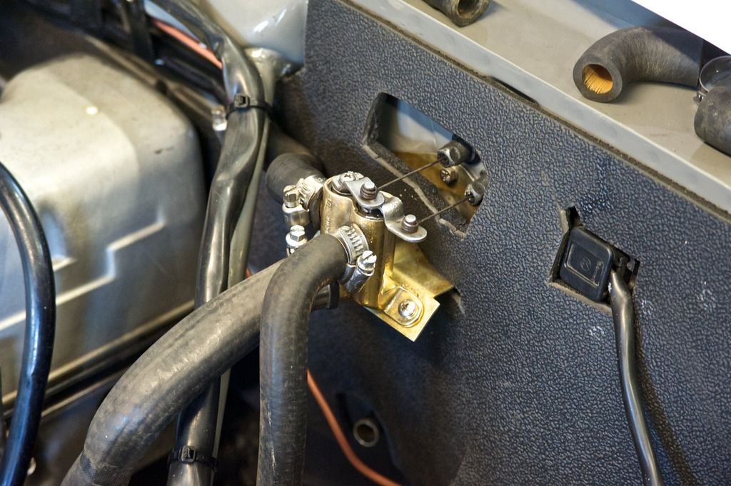
Idle Air control Valve ("IACV")position is the current headache, but I think I am getting there, inspired by a discovery when last up at CCPS.

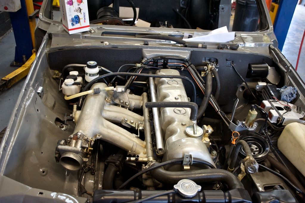
The current idle control is entirely mechanical - the first photo below shows the line from air intake housing to manifold (bottom left to about 35% up right side).

The problem is the weight of the IACV. It weighs just under a pound, and would need a mounting (plus a wider hose). My BMW M535i has a bracket for it and my SM has it mounted on some seriously thick hose, with half the span of hose than on the 114. Second photo shows the difference in hose size.

Anyway back to the first photo - mid-way up on the left side you'll notice the cold start injector on the side of the manifold. This is now redundant with MS (and I have a back up). Removing the injector itself reveals a nice possible mount for a hose to the air inlet - drill a wide hole, weld in a pipe through it to the outside, then do the same on the underside of the air intake and mount the IACV where the MAP sensor (an equally lumpy and hefty thing) sits on the inner wing. Guaranteed to cause bafflement and searches in the marking boxes of a concours judging sheet of the men in white short sleeved polyester shirts perhaps?

(apologies for photos, photobucket is being so slow I've give up today).
 

Attachments

  • idleACV.jpg
    idleACV.jpg
    45.4 KB · Views: 19
  • IACV vs existing pipe.jpg
    IACV vs existing pipe.jpg
    105.5 KB · Views: 16
  • cold start injector.jpg
    cold start injector.jpg
    188.8 KB · Views: 12
Last edited:
What restrains the cold-start injector? Can it not be tweaked to accept the hose without having to weld the manifold?
 
The injector mount on to the manifold is what I'd weld, but removing the injector from its housing entirely would leave a nice pipe width in, so thanks for the improvement!
 
No - the Idle Air Control Valve is a device that opens as required to let air into the manifold while the engine is at idle, bypassing the closed throttle butterfly. The stepper motor inside is controlled by the ECU to maintain a steady idle, opening and closing as required. The existing mechanical set up will go as it is entirely redundant.
 
Last edited:
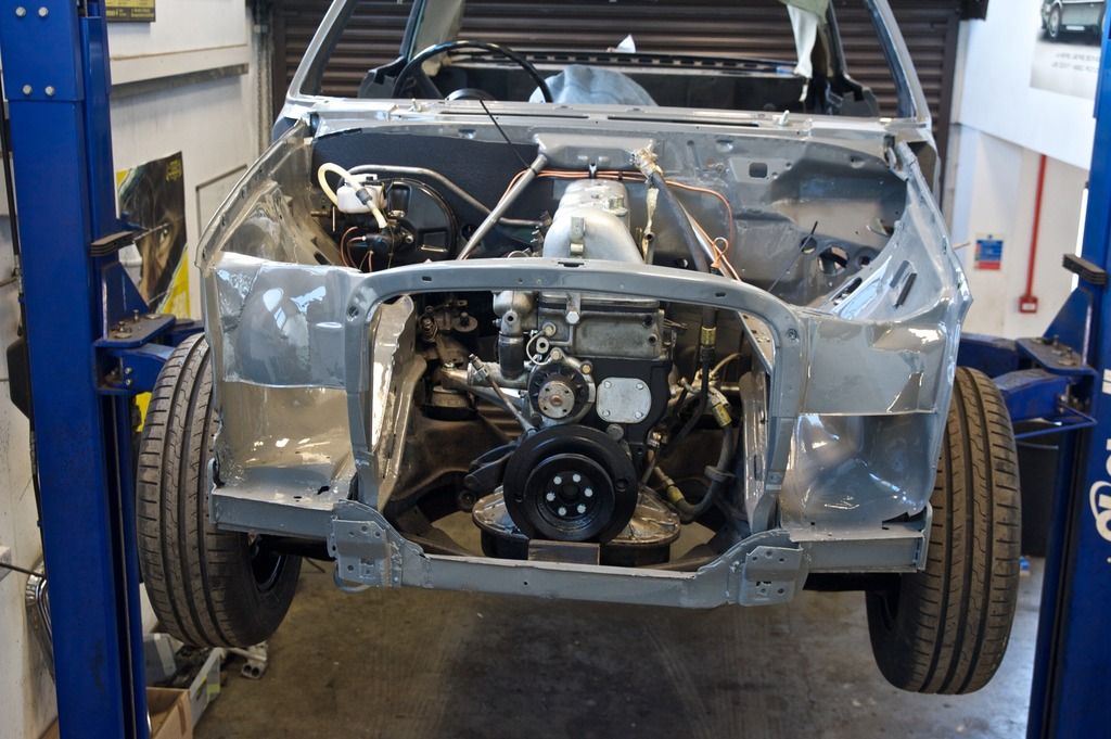
Lots of progress but little time to report. Photos to help in the meantime.

comingonW1146_zpszyg39li7.jpg


comingonW1145_zpsz1mhgydv.jpg


comingonW1144_zps1nzmyflu.jpg


comingonW1143_zps4asnlfgr.jpg


comingonW114_zpscxkghkzu.jpg


comingonW1142_zpskwfmqmfs.jpg
 
Last edited:
Bolted not brazed?


Those relays - cunning!
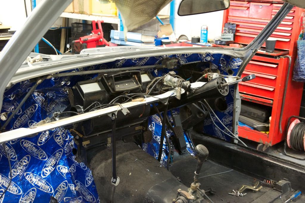
Firewall insulation looks good - as does all the progress. You're getting there.

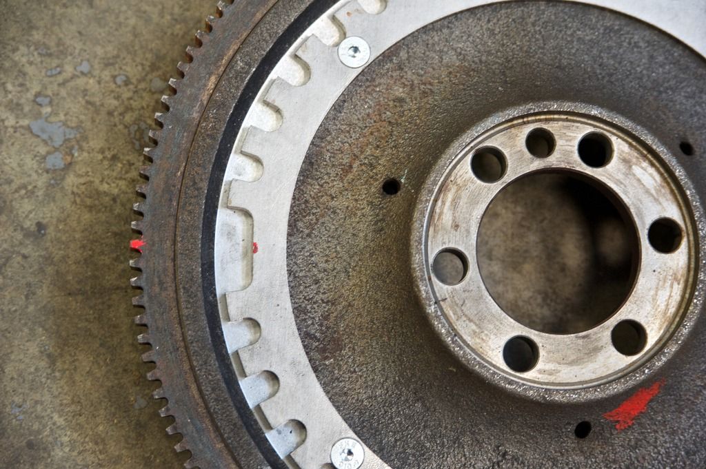
The machine shop decided that the face of the flywheel was not flat enough so they chased in the trigger wheel. Bolts ensured it was balanced, which it has turned out to be, perfectly. It's a very nice piece of work.

I'm really pleased, the chap now working on it is intelligent, knowledgeable about old and new car systems and is not prepared to cut corners. He has been really helpful on planning the MS conversion too, and when I explain something he grasps it instantly, which is reassuring to me that I'm not spouting total nonsense, and invariably he has a better plan.
 
Last edited:
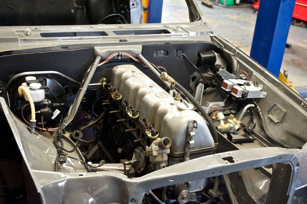
In case anyone was wondering the cam cover pictured is not going to be the one going on finally, it's simply protecting the gubbins underneath. I am hand-polishing one to crown it all off.
 
Thanks Graeme - a lovely period resource!
 
All my Megasquirt bits and pieces (ECU and other bits) have now been ordered from Phil at ExtraEFI. He has been exceptionally helpful, and his website has a huge number of useful how to videos.
 
A nice pair of pressed black and silver aluminium plates also ordered.
 
I spent most of the day helping with the restoration work up at Bicester as identifying and fitting a lot of hoses etc required my knowledge.

Duovalve (beautifully polished by Iwan, the new apprentice) and heater pipes all in.

duovalve%20in_zps0f1n16th.jpg


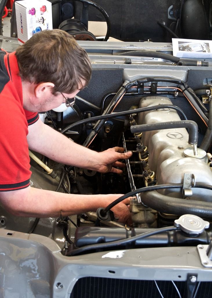
John fitting the manifold gasket (one stud was slightly out of true so this was a bit tough)

fitting%20manifold%20gasket_zpsmqb47njy.jpg


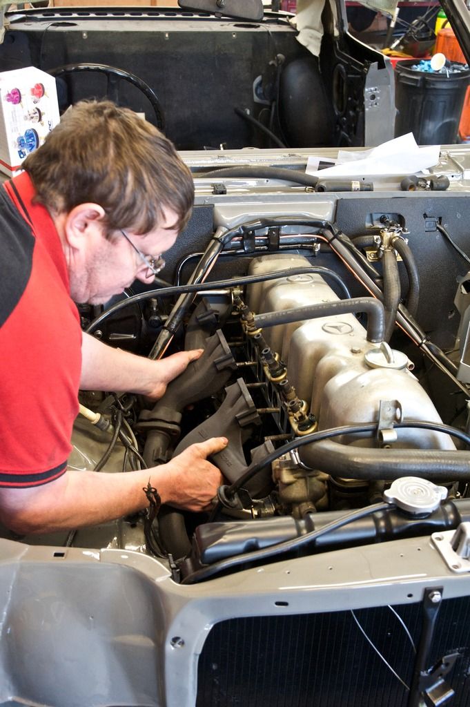
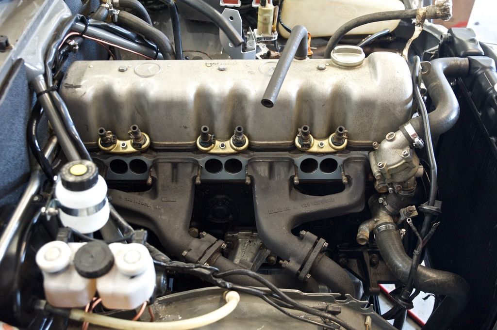
Next the exhaust manifold - very tight, so we had to remove the bolt holding the o/s engine mount and pull the engine over to the n/s enough to create some space.

fitting%20exh%20manifold_zpsttrakguu.jpg


In

fitted%20exh%20manifold_zpskposq4vk.jpg
 
Last edited:
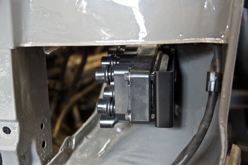
Doesn't look like the original ignition amplifier, I wonder what this is?

coilpacks_zps0kvupqvc.jpg


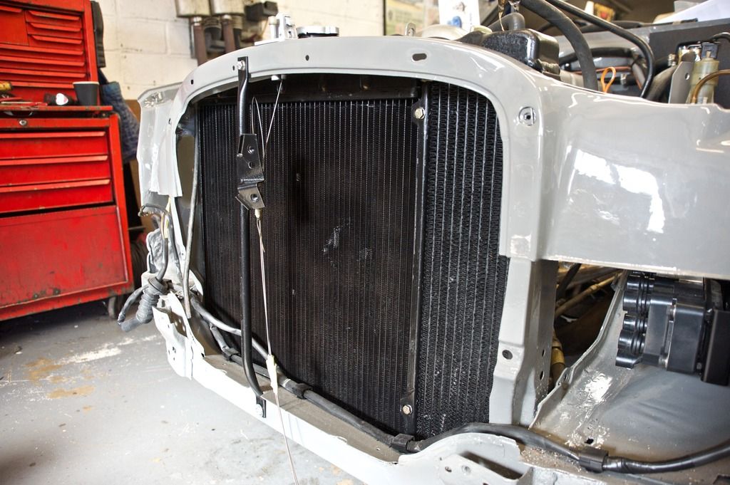
Radiator and oil cooler all in:

radiator%20in_zpsmwifjllu.jpg


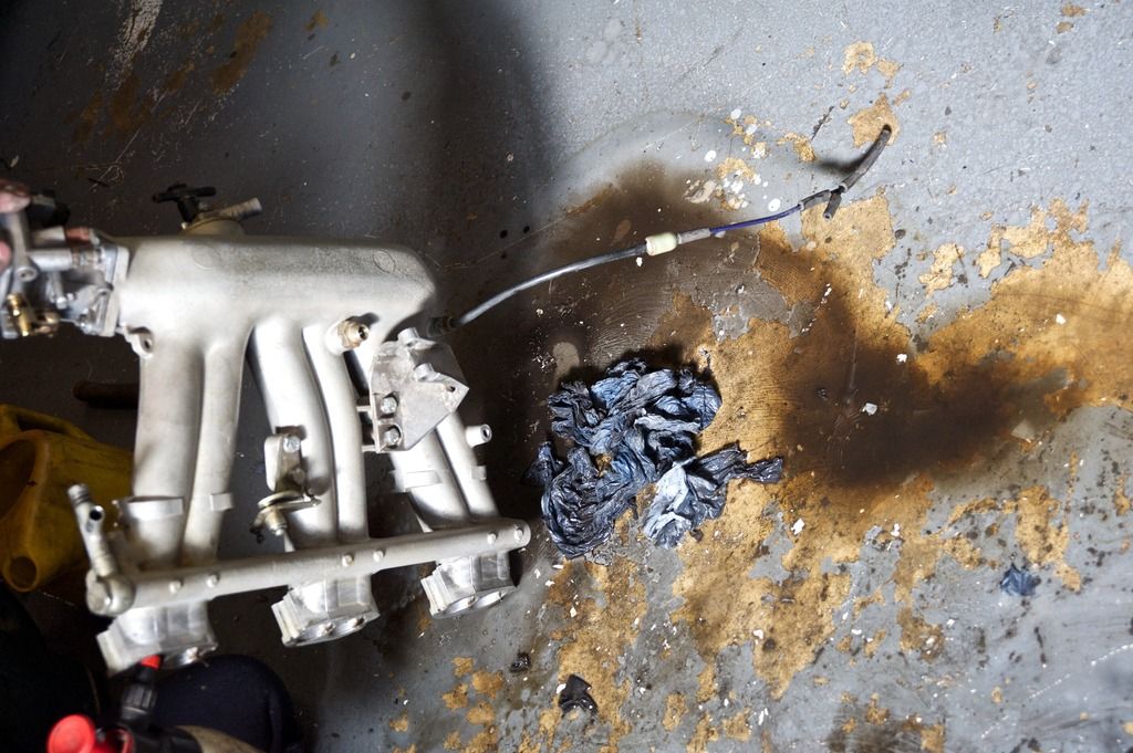
What brake cleaner pulled out of the inlet manifold

manifold%20crap_zpsj1ia3lxq.jpg


Inlet manifold completes the day's exciting activities.

All%20in_zps1g6dcint.jpg
 
Looking fantastic Charles. Great work.

Sent from my iPhone using MBClub UK
 

Users who are viewing this thread

Back
Top Bottom