• The Forums are now open to new registrations, adverts are also being de-tuned.

Mercedes W114 250 Coupe - help!

Well I'm not going to overturn overnight a policy that continues until well into the 90s of absurdly low ratio gearing. I shall live with the manual and see how I fare. If I find it droning then there are better ratios diffs from W114s or W123s that can be slotted in relatively painlessly.

How they charged up and down autobahns at high speeds with all that revving and droning is quite beyond me.
 
By my calculation*, you should have 21.79mph/1000rpm in 5th, 18.96mph/1000rpm in 4th.
80mph would see the engine spinning at 3670rpm.

*Calculation assumes sidewall height is 0.65 x 195mm, and twice that is added to 15'' for rolling diameter.
 
So at 70, approximately 3200. A 3.69 would be would have been so much nicer at almost exactly 3000.

It's liveable. I've found a 3.5 ratio diff should it turn out not to be!

What I found when I changed the Allard's diff ratio from 4.11 (did the earth move for you or was that just the car shaking itself to bits?) to 3.25 (I might be able to make it to the next petrol station in 20 miles with a quarter tank) was that first became a really useful gear (except when needing to downshift to it - without syncro that was always fun). You could actually keep it engaged until you had enough road speed that you wouldn't come to a halt while trying to find second...
 
Last edited:
I once drove a van (MB) that had a crawler first gear that I only ever used to turn right at an uphill junction when laden to full weight. The rush to select second as it ran out of revs risked stranding me straddling the road with oncoming traffic.
Worse was making the move in second, realising it was stalling and reaching to engage the crawler the second before it did, and being rewarded with a sharp crack over the knuckles from the walloping gear lever. Happy days...
 
Can I ask Charles how useful was the DVD you got from the Mercedes-Benz Club? Did it contain the wiring diagram for the D jetronic 250 CE?
 
Last edited:
I can't really gauge the usefulness just yet Graeme as we've put the electrics on a bit of a back burner. However, the wiring diagram is the same as on Bolinko, so I hope that is correct!

I'm just back from Bicester and will soon be out again for choir in half an hour, but an immensely useful session today. We worked out where TDC is for the flywheel (not an easy task), then determined the exact position of the missing tooth of the trigger wheel (which has to be an exact 60 degrees in advance of sensor location at TDC), so were able to get the flywheel to the machine shop to have the trigger wheel brazed onto it (then possibly balanced). Once done the engine is going in. The great thing is the space to work in the engine bay is considerable, so no work will be held up by the engine going in.
 
Last edited:
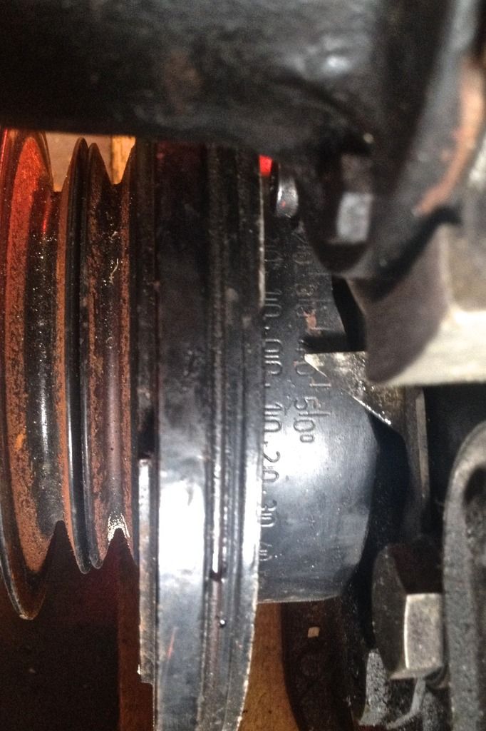
To determine accurate sensor location for the CPS at the flywheel, first catch your TDC as Mrs Beeton might have said if she'd been a mechanic. Helpfully some nice chap in Germany had put this calibrated wheel on the front crank which, oddly, showed 0|0 at TDC on the inlet stroke (we checked with piston and cam position too, just in case).

TDC_zpscqttn6od.jpg


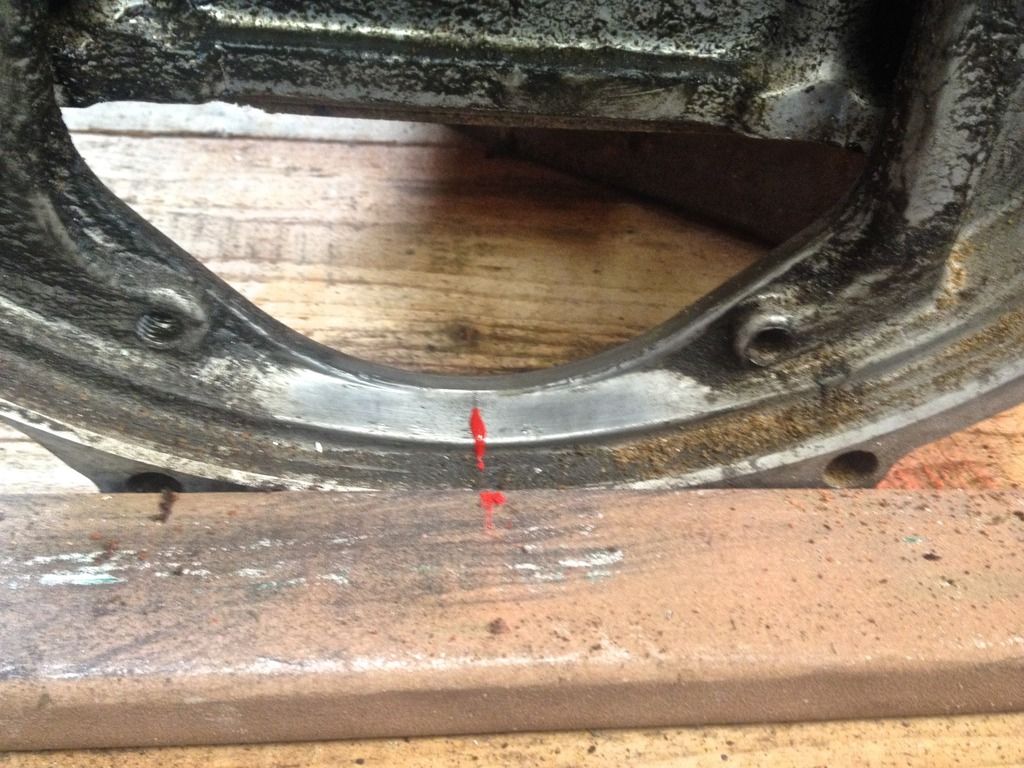
Very unhelpfully the flywheel was not organised in such a nice Germanic way with marks and dials, and worse, the bolt pattern was not helpful. So, first we estimated where we were going to put the CPS, half way along the back plate inspection hole.

sensor%20position1_zpsquz1xxvc.jpg


Given that the gap toothed bit of the triggerwheel needs to be 60degrees in advance of the CPS location, we marked a further 10 degs on the timing wheel (it goes out to 50 retardation) and with the timing wheel at 60 degrees we marked the position on the flywheel that corresponded to the CPS marked position.

sensor%20position2_zpsabsepbfk.jpg


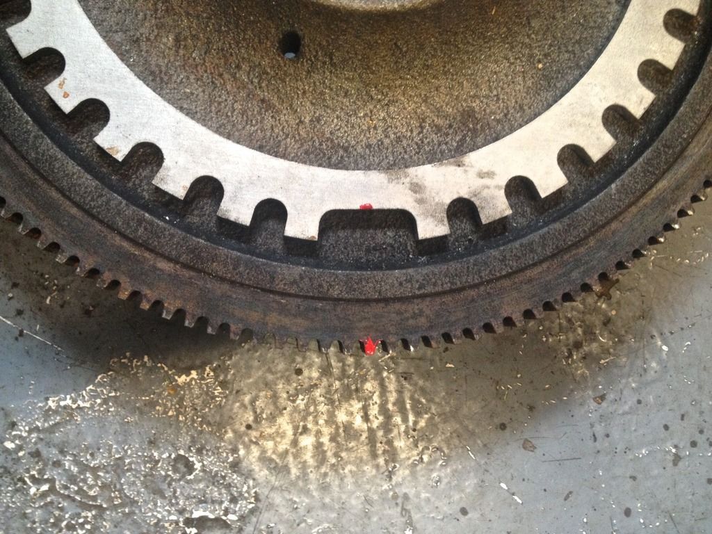
The red mark on the starting ring teeth (painted on the back then marked at the front) then becomes the datum line for exactly half way along the gap tooth (which were there to be a tooth there, it would bisect it). When put back to TDC, the flywheel will be advanced 60 degrees ahead of the CPS location.

Now all this has a measure of imprecision, but when the trigger wheel is attached to the flywheel (if done accurately, which I expect) the CPS location will be determined by the half way point on the tooth 6 on from the centre of the gap. So we can adjust the CPS position precisely from that.

I think...

In other bits of progress, found out where and what thread the coolant temperature sensor needs to be. Another interesting tidbit - the manifold on the slightly later engine bought from Germany (at least I believe it so) is almost exactly the same as the one from mine, but for the linkage pivot in the centre - my old engine has a pivot that makes the pedal travel non-linear, so the first 50% (estimated) of movement of the pedal makes for only 30% movement of throttle butterfly. Whereas the later manifold it is 1:1 all the way through the pedal movement. Which means I have a choice as to how linear I want my throttle. Choices choices...
 
Last edited:
Given that the gap toothed bit of the triggerwheel needs to be 60degrees in advance of the CPS location, we marked a further 10 degs on the timing wheel (it goes out to 50 retardation) and with the timing wheel at 60 degrees we marked the position on the flywheel that corresponded to the CPS marked position.

Now I understand why the 60 degree offset - cunning!

Another interesting tidbit - the manifold on the slightly later engine bought from Germany (at least I believe it so) is almost exactly the same as the one from mine, but for the linkage pivot in the centre - my old engine has a pivot that makes the pedal travel non-linear, so the first 50% (estimated) of movement of the pedal makes for only 30% movement of throttle butterfly. Whereas the later manifold it is 1:1 all the way through the pedal movement. Which means I have a choice as to how linear I want my throttle. Choices choices...

Could the differing ratios be due to manual or auto application?
 
Good question, we don't know whether the engine came from a manual or an auto, but given the clutch marks all across the flywheel, we think it's a manual.
 
my old engine has a pivot that makes the pedal travel non-linear, so the first 50% (estimated) of movement of the pedal makes for only 30% movement of throttle butterfly. Whereas the later manifold it is 1:1 all the way through the pedal movement. Which means I have a choice as to how linear I want my throttle. Choices choices...
That's a no-brainer imho. The non-linear motion will make for smoother traffic driving whereas...how often do you actually use more than 1/2 throttle. Not often I'll bet.
 
Scratches head and still not certain he computes the above...

I want a throttle that goes from 0-100% in no real distance, with a connection to the brake pedal once I lift, it's how I drive...
 
Theme of the day (when I get back this evening) will be sensors and MS bits. The coolant temperature sensor I located Monday is easily replaceable being M12. The air intake sensor is an M8 size, which I now believe to be redundant. Either I check the operation (resistance table for DJet air intake sensors anyone) or I get the location on the air filter out pipe drilled and tapped for a standard one.

The Idle Air Control Valve I bought is just way too big and heavy for placing on a rather narrow rubber pipe. I am not sure I want to keep buying parts randomly off t'internet but will give this a bit more thought.

Remaining bits on fuel rail - tap it for injectors and fuel lines, plus find an FPR that will fit - I think I'll mount it directly at the end of the rail.
I would caution against mounting any electromechanical device such as a relay on the engine itself where it may be subject to extra heat and vibration.:dk:

PS do you mean the the air intake temperature sensor when you say "air intake sensor"

quote:- Air Temperature: The density of air is a function of temperature and the basic injection quantity must be corrected for the effect. In the D-Jetronic system, the TS1 sensor is a negative-temperature-coefficient resistor (resistance goes down as temperature goes up), mounted on the intake plenum. The ECU uses the value of the TS1 resistance to correct the injection quantity for the effect of temperature.

https://www.rexbo.eu/bosch/sender-unit-intake-air-temperature-280130006
 
Last edited:
Bosch more modern NTC Sensor- I imagine the older one is similar

Description
High quality "NTC" type air temperature probe manufactured by Bosch. Overall length of 49mm, and a fitting thread of M12 x 1.5mm pitch. The resistance of the sensor changes with temperature. a "pull up resistor" may be required depending on the circuitry fed.

Technical Data
Measuring Range -10°C to +100°C
Permissible Temp max °C +130
Electrical Resistance at 20°C (kohm) 2.5 ±5%
Electrical Resistance at:–10°C(kohm) 8.26...10.56
+20°C (kohm) 2.28...2.72
+80°C (kohm) 0.290...0.364
Nominal Voltage (V) ≤5
Measured Current,max (mA) 1
Self-heating at max. permissible power loss P=2mW and static air at T=23°C (°C) ≤2
Thermal time constant *1 approx 20s
Guide value for permissible vibration acceleration (sinusoidal vibration) (m·s-2) 100

*1 At 20°C. Time required to reach 63% of final value for difference in resistance, given an abrupt increase in air temperature; air pressure 1000 mbar; airflow rate 6 m · s-1
 
Wiring and Sensors
scroll down to the temperature sensors section which details how the AIR TEMP SENSOR interfaces to the controller- unfortunately speaks mainly about GM temp sensors whose characteristics are better known.
 
I think I'll drill the air intake sensor mount (make the wider hole stable with a bit of welding including the correct nut) and fit a modern sensor with known resistance values. Unless I can be certain the DJet one is producing consistently correct resistance
 
I think I'll drill the air intake sensor mount (make the wider hole stable with a bit of welding including the correct nut) and fit a modern sensor with known resistance values. Unless I can be certain the DJet one is producing consistently correct resistance

Sounds a good plan. Its going to be easier to replace also should it go faulty or get broken.
 

Users who are viewing this thread

Back
Top Bottom