• The Forums are now open to new registrations, adverts are also being de-tuned.

Mercedes W114 250 Coupe - help!

picture of the fuel rail attachment from the old 280 thread.

the new

attachment.php


the old

attachment.php


you can actually see the 3 black U shaped brakets that attach the fuel rail top and bottom better here .


THE THOUGHT NOW OCCURS- If the injectors are now retained firmly both in the cylinder head/manifold [ front end] and effectively sealed into the fuel rail [ rear end] by the new rigid fuel rail is there any need for the old injector retaining plates ? - could the mounting bolt holes for said retaining plates not be used as mounting points for 3 fuel rail retaining brackets? these would then have dual function- keeping the injectors in place and sealing on the fuel rail? Or is that too easy?

attachment.php
 
Last edited:
picture of the fuel rail attachment from the old 280 thread.

the new

attachment.php


the old

attachment.php


you can actually see the 3 black U shaped brakets that attach the fuel rail top and bottom better here .


THE THOUGHT NOW OCCURS- If the injectors are now retained firmly both in the cylinder head/manifold [ front end] and effectively sealed into the fuel rail [ rear end] by the new rigid fuel rail is there any need for the old injector retaining plates ? - could the mounting bolt holes for said retaining plates not be used as mounting points for 3 fuel rail retaining brackets? these would then have dual function- keeping the injectors in place and sealing on the fuel rail? Or is that too easy?

attachment.php

By coincidence (honest!) I have come to a similar conclusion, although I would prefer to retain the old injector retainers as I think a bit more rigidity is not a bad thing, but that could easily be added to brackets as you can just trim a bit off the end of the retainers to allow for the bracket thickness. I'll have a play around with the spare head this weekend and see if that would work.
 
Doesn't work, what is difficult to see is that the throttle bar has a lever (to the left of the opaque plastic pivot) that juts out about an inch from the bar at the bulkhead and as the throttle is depressed the lever rises and fouls the fuel rail which sits a lot lower than the old one). Shifting it over a small amount ensures good clearance.
 
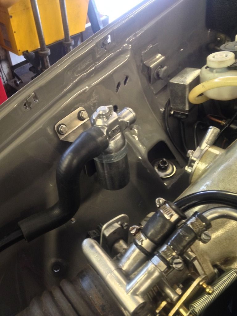
Spent the day sorting out things on the car, roof rails are now completely polished and will be bolted on to the car. Meanwhile the Idle control valve has found a home where the old MAP sensor used to be. Seems to fit in nicely! The out pipe will be plumbed in to the air inlet valve for the old cold start injector visible on the right.

The air filter housing has been adapted to create a larger pipe but no photos as the welds need a bit of filing. It is going to look almost completely OEM.

Talking with John today we will fabricate some brackets for the fuel rail and also use the injector brackets as we think them essential for keeping the injectors secure.

idlecontrol_zpsvxhxykuc.jpg
 
Last edited:
Blimming heck, just bought a couple of bits and pieces from Germany that I needed. Most of my purchases last year and early this year were between 1.30 and 1.40 €:£, with the majority closer to 1.40. Just got whacked for 1.21.

Glad I did most of my parts shopping when I did!
 
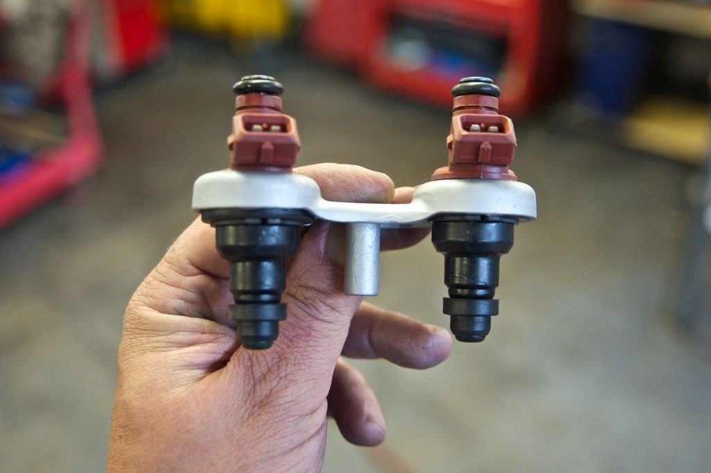
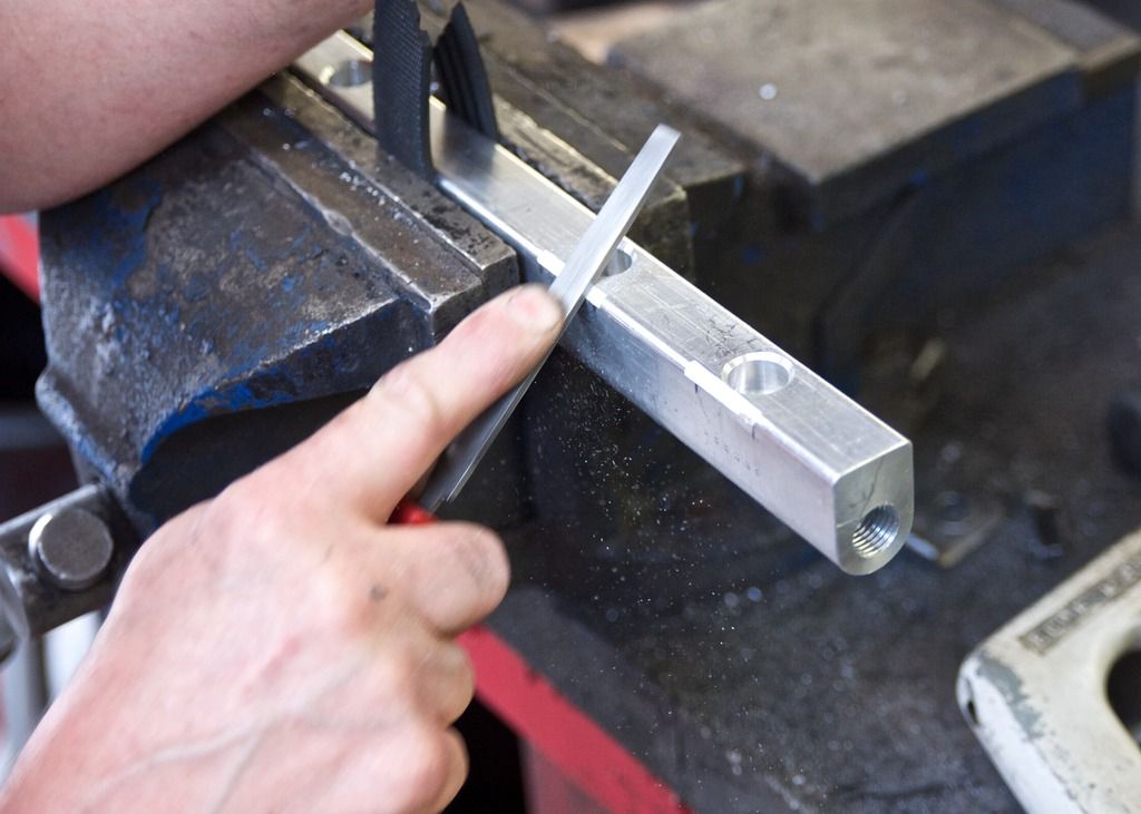
Fuel rail progress. Using the old D jet injector brackets, rubber grommets and circlips, plus the D Jet injector pintles and rubber holders, the new injectors were mounted on the brackets. Could have been made for them!

injector%20bracket_zpsgc8ghegi.jpg


Fitting nicely while we ponder the rail mounting arrangements.

injector%20brackets_zpsk2vl50v8.jpg


The space between the cam cover and injector terminals is just too tight to be able to remove the connectors so a little filing of the fuel rail to make life easier.

fuelrailfile_zpsorq8fghd.jpg


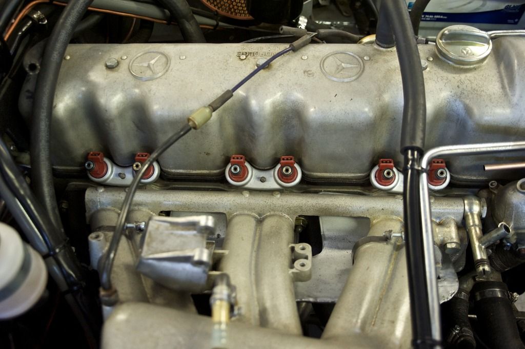
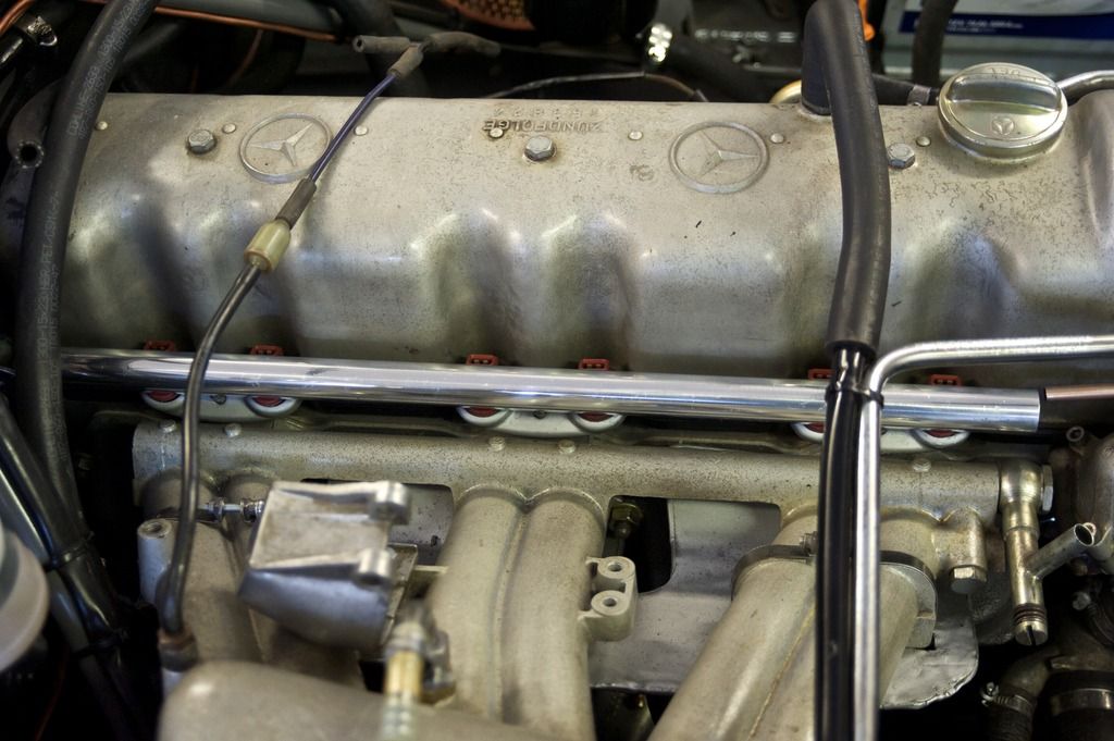
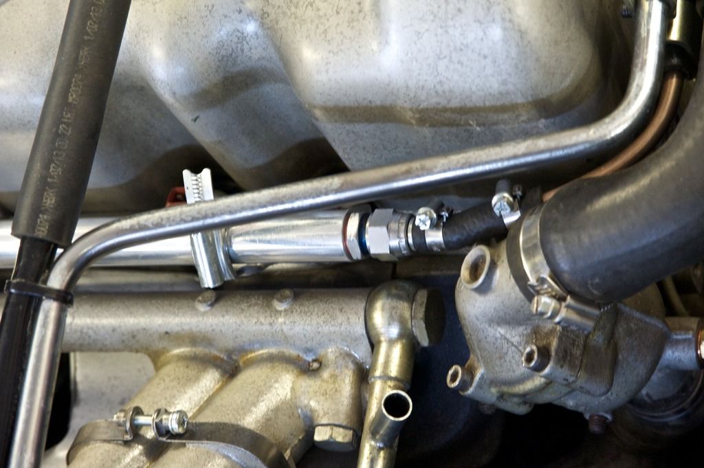
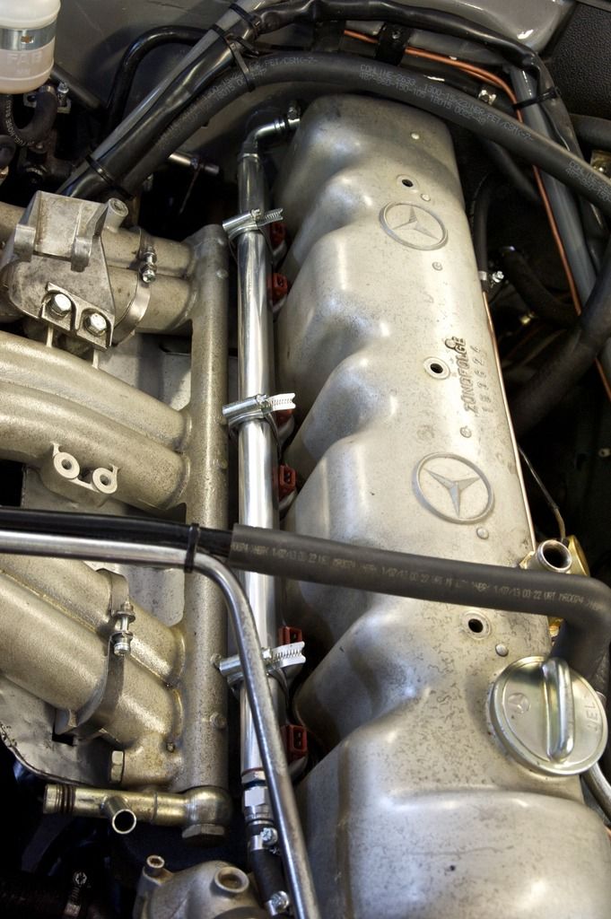
Nicely polished and mounted, the fuel rail awaits solutions to the fuel pipe tightness at the rear (throttle bar) and front (thermostat housing gets in the way) and to the mountings, but when put on the injectors it is a pretty rigid arrangement.

fuelrail_zpswqsgpclc.jpg
 
Last edited:
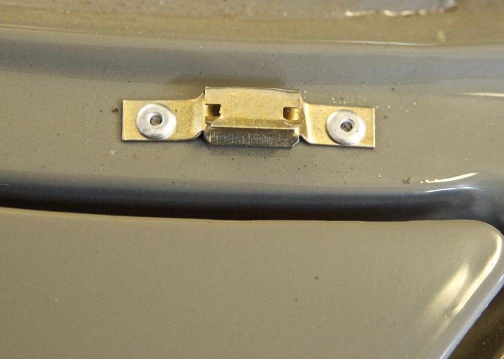
I decided to improve my skills and learned to something positively riveting at the same time.

My first riveting experience, the rear screen trim clamps.

rivet_zpseulg7kkw.jpg


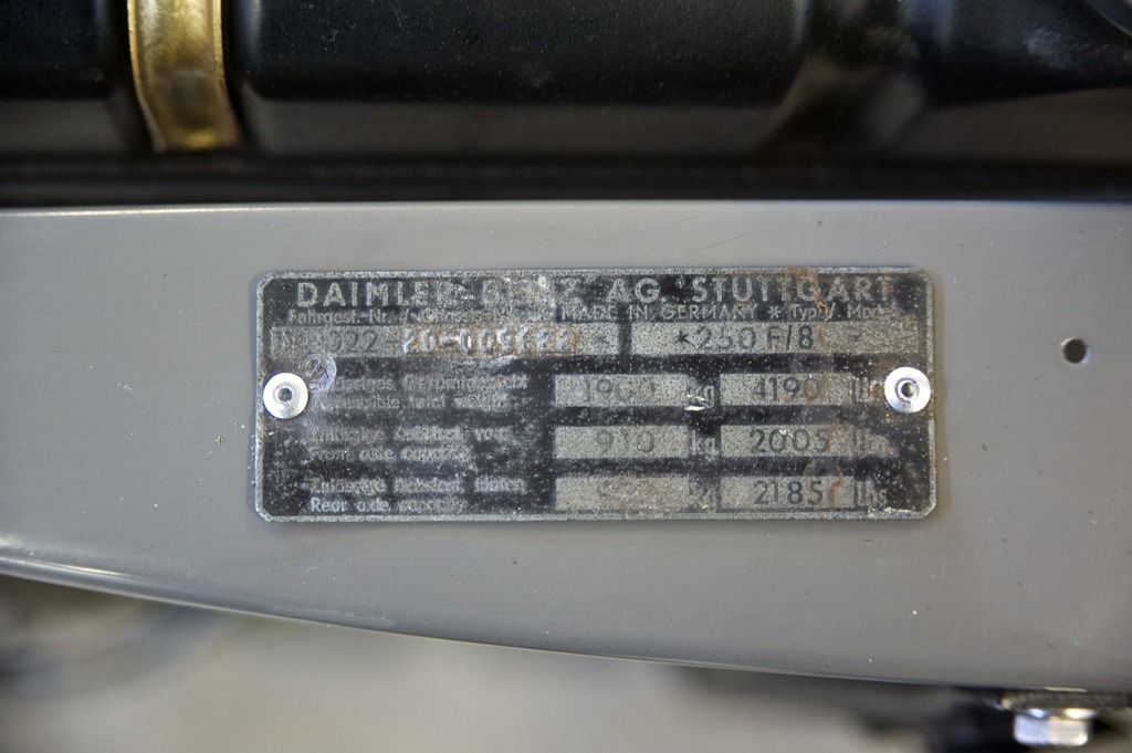
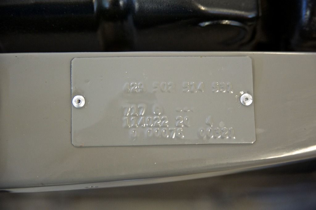
Then really exciting, reinstating the chassis plate and colour code plate (which is of course entirely wrong).

rivet2_zpsol54abn5.jpg


rivet3_zpsrgk1zax4.jpg
 
I have to confess to worrying about fuel rail and injector clearance with that very large cam cover in place but looks as if you have found the solution. There appears to be quite a bit of fuel rail surplus length front and back [ more at the back] Could the rail length be shortened to facilitate clearance?
 
We are going to take off about 1.5 cm at the front, more and the tap for the fuel pipe connector will get too close to the first injector. It's all tight, but I think we'll get it all fitting.
 
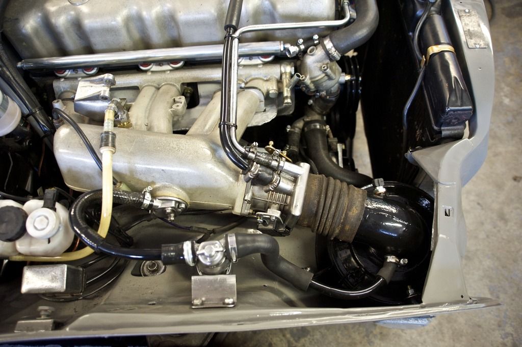
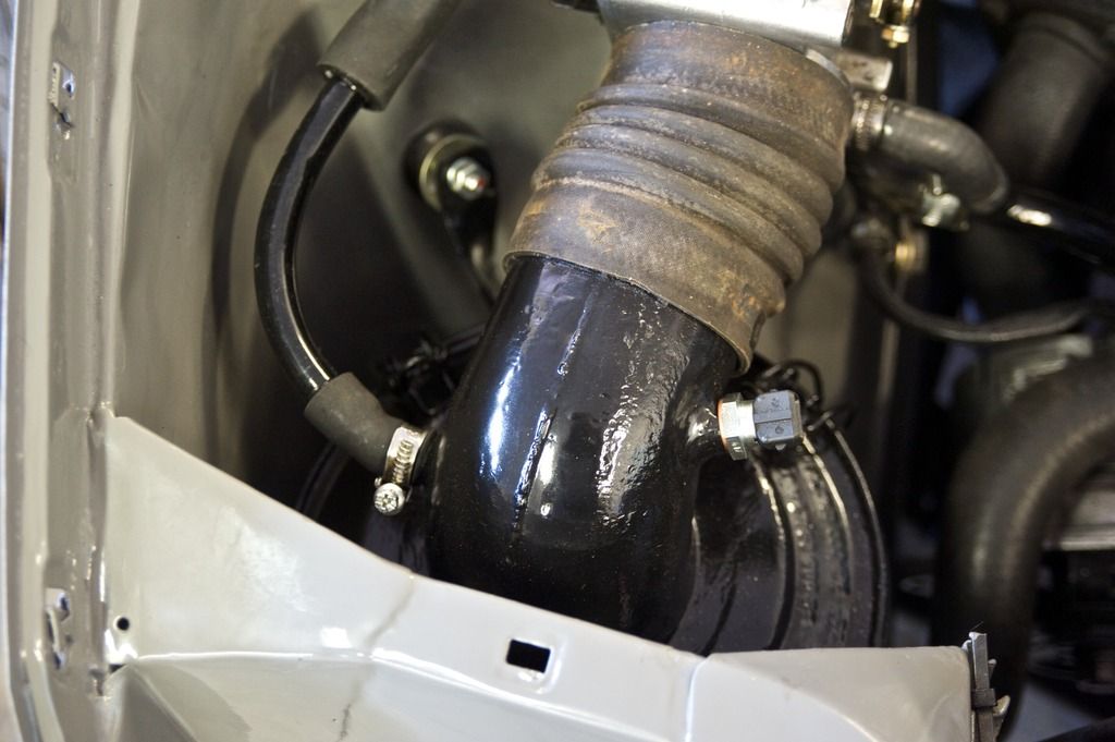
Mucho progresso today. Airbox has been mounted with the air intake and sensor mounting moved, so all the idle control arrangements are on.

engine%20bay5_zpszs15vrmm.jpg


engine%20bay6_zpsr3iplcxh.jpg


Just needs another good clean and some large jubilee clips and the air intake now connects to the throttle body.

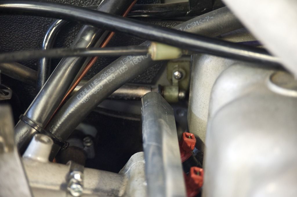
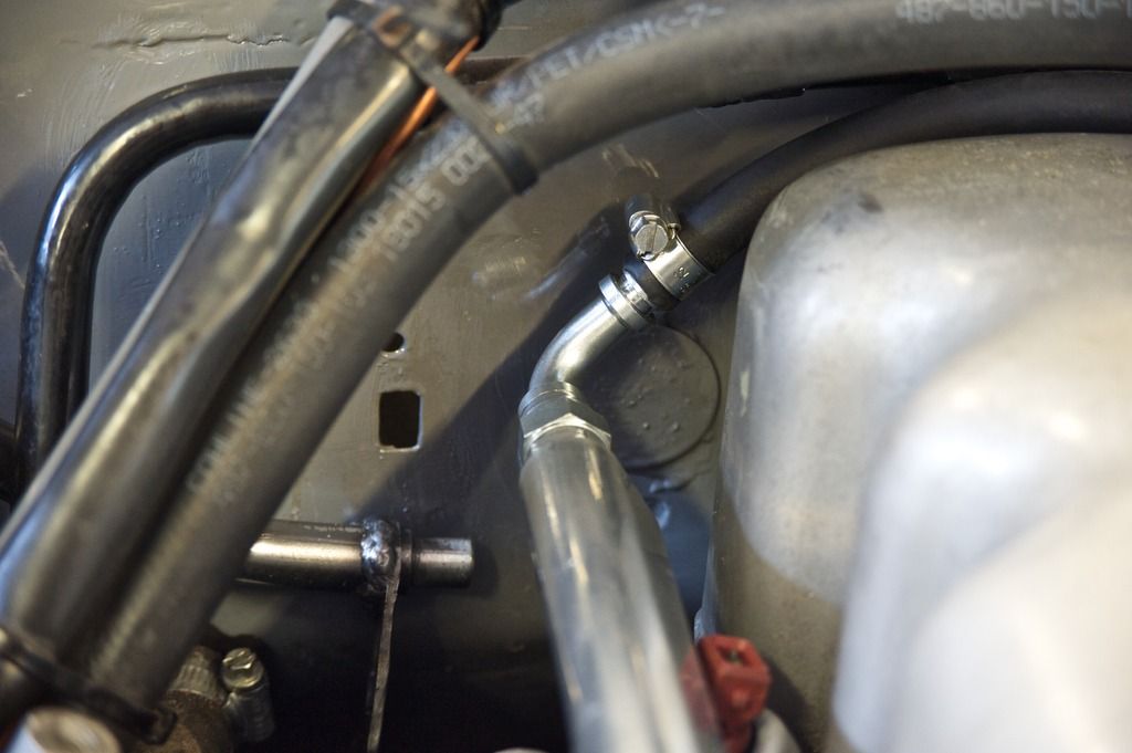
Fuel rail was completed today. We moved the throttle bar over and shortened it a bit, which gives enough clearance for the fuel pipe to come out of the fuel rail and behind the cam cover (the angle upwards helps - there is a concavity in the firewall that gives enough room for the pipe to get through.)

engine%20bay4_zpsp1julpwy.jpg


At the other end a reduction in the fuel rail length and a shortening of the connectors and lo, it just fits round the thermostat housing.

engine%20bay3_zpsymbxnxym.jpg


The rail mounting brackets are proper Jubilee clips, held in by the stud that holds the injector brackets, with a thicker piece of metal at the base to stop the jubilee clip from bending. All that is held in place with a nylock nut each to ensure it isn't going to move.

engine%20bay2_zpsx6ua4p6g.jpg


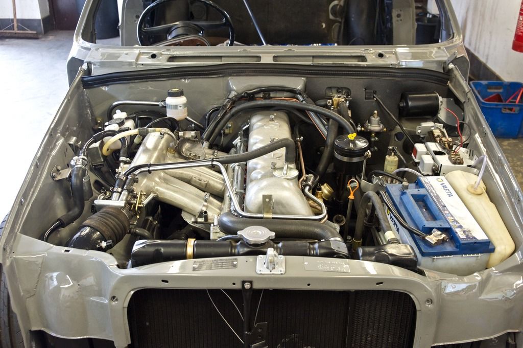
The jubilee clip was squared off before mounting and then it is tightened over the rail, with counter torque provided by a long spanner on the rail. When all tightened up it's totally immobile even with a foot long spanner twisting it. Fuel rail is easy to remove and the Jubilee clips are small enough to work in the tiny space available, and the ends will be used for mounting the injector wiring. Result, one completely modified engine bay. Now to get the loom in.

engine%20bay_zpszuuy9ut1.jpg
 
Sorry Charles but first bit of criticism for you coming from me.

That fuel rail hold-down is a bodge.
 
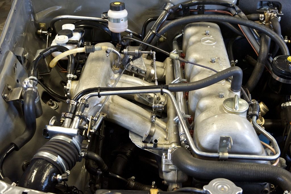
Excellent progress Charles. :thumb: I take it the 2 large jubilee type clamps round the outer/inner inlet manifold arms are to locate that heat shield between the inlet/fuel rail and exhaust manifolds? Looking forward to the "wiring" ;)
 
Last edited:
All the throttle linkages in. ECU and EDIS controller brackets fabricated yesterday so mounting the ECU and getting the loom in is the next task.

throttle%20linkages_zps6m5dus66.jpg
 
As per Druk, a bodge. It's not good enough using common hose clips to locate the rail on a quality build like this (it's not good practice regardless), it's the first thing anybody would notice the second the bonnet is opened too - brings the whole EFi retrofit job into question.

A possible simple solution is to fab two/three/four right angled brackets that attach to the inlet manifold bolts and press down on the rail. Slot the inlet manifold bracket hole allowing movement/adjustment up & down and fit a half moon block to the opposite end of the bracket with a bolt that may can also be used to adjust the pressure of the bracket/block on the fuel rail.

Now, that was easy to write and would take a bit of time to actually make but it's simple that's the important part.

Whatever, there is a better solution out there.
 
double post
 
Last edited:

Users who are viewing this thread

Back
Top Bottom