• The Forums are now open to new registrations, adverts are also being de-tuned.

Mercedes W114 250 Coupe - help!

Even consider using the rocker cover bolts with an extension piece welded to the original bolts. The extension on top of the bolts could then be employed to apply pressure against the fuel rail with some sort of bracket/arm.
 
Oh yes, just proving to be a pain to upload (photobucket has become impossible). I also forgot my camera one day as the loom work was starting.

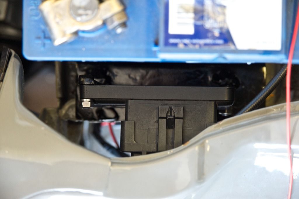
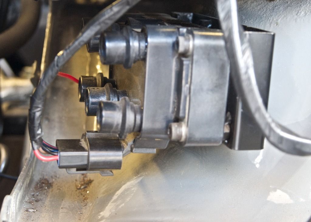
ECU to EDIS controller to coilpacks now wired in and all mounted on brackets

w114EDIS_zpsyl6jb7yb.jpg


The EDIS controller bracket is attached to the top of the battery plate at the front, and the coilpacks underneath. Next job the HT leads.

w114EDIS2_zpsgt6vmxci.jpg


Power leads to injectors.

W114injector%20loom_zpsmacmgza7.jpg


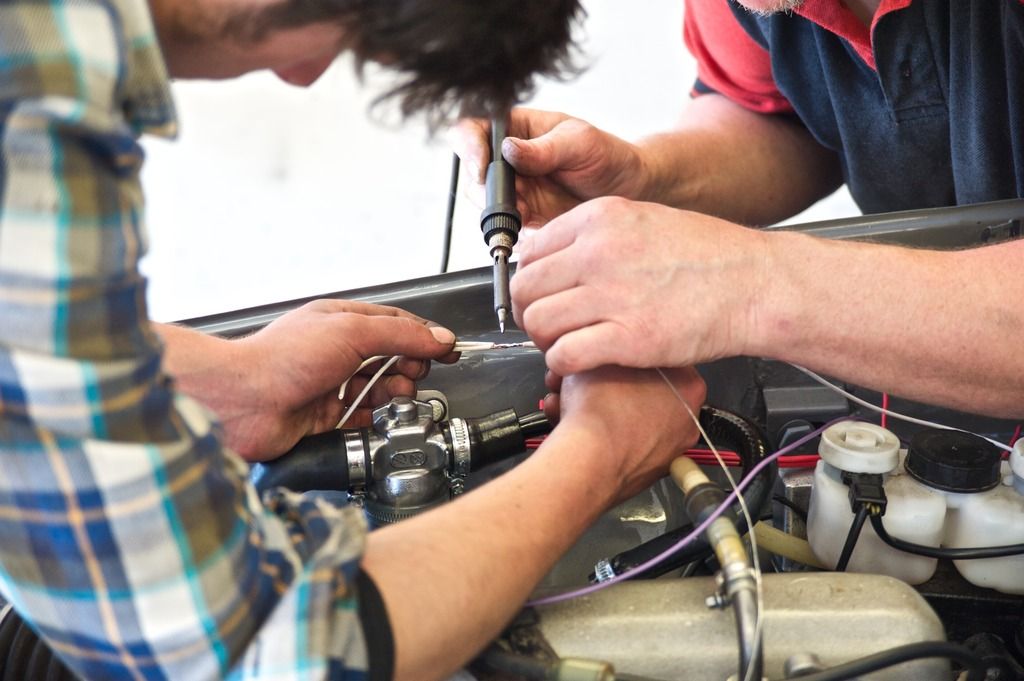
Soldering the earth connections for injector bank A (they earth to the ECU)

W114injectorloomA_zpsteyao5fn.jpg


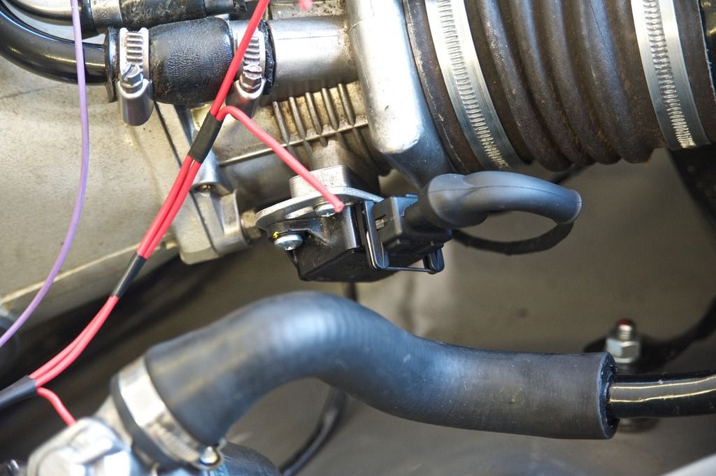
TPS connector now done (as is Air intake sensor).

W114cpsloom_zps55nvtzxk.jpg


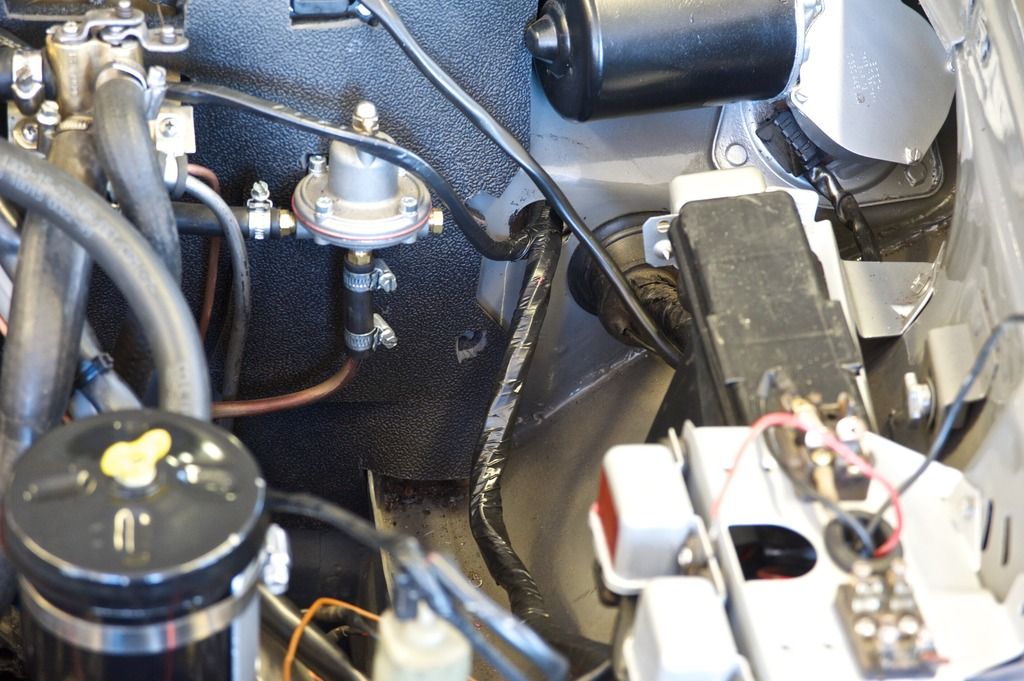
Main MS loom going through the bulkhead using the old DJet hole

W114%20loom_zpsn6pise0m.jpg


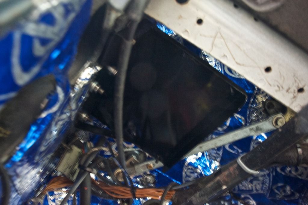
ECU bracket (under dashboard by N/S bulkhead) - the orientation enables the loom to go through the bulkhead easily but lets the USB connection face the cockpit.

W114ecubracket_zpstmbxcxcm.jpg

Not shown but the CPS is wired into the EDIS controller with shielded cable, as is the SAW cable to the ECU. I now have 29metres left over (minimum order of shielded cable 100ft!).

The idle control valve requires quite a large power resistor (50w 25ohm) for grounding it so I found them on sale in the UK for not much but you needed to order a 1000, so one is on its way from the US.

I fully expect all the loom to be finished tomorrow. Sadly the existing wiring is incomplete in a lot of places and proving a bit of a pain, but we will get there.
 
Last edited:
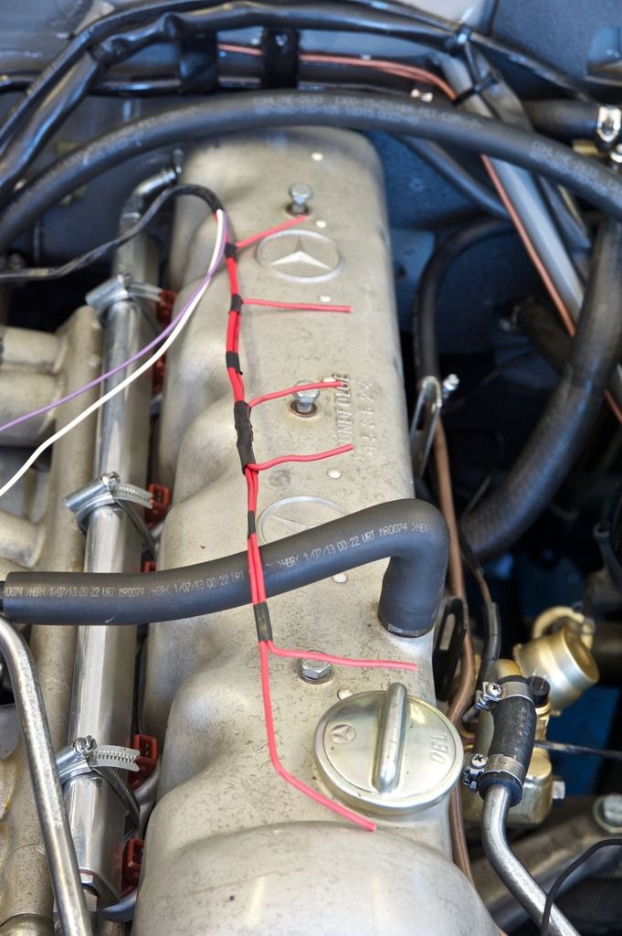
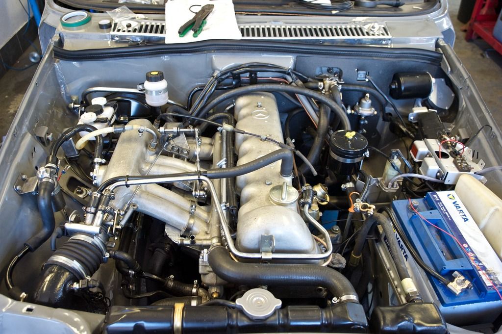
Injector loom complete now.

W114%20loom2_zpsmefziy4j.jpg


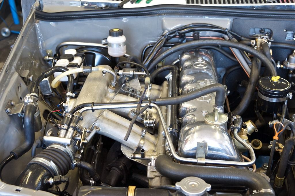
But I thought the cam cover could do with a quick rub down to get it a bit shinier.

W114%20loom3_zpsqjkphemv.jpg
 
Forgotten that! It's the progressive one from the UK manifold rather than the linear one from the German engine. A swap takes minutes if I want to experiment.
 
That open pipe to the fine idle bypass pipe looks a bit forlorn. I take it it's now redundant with the motorised idle control valve and its connection to the main inlet pipe occupied by a sensor[ air intake temperature?] I assume its effectively shut off with the valve screwed right in but would look neater capped off with something??
 
I fully expect all the loom to be finished tomorrow. Sadly the existing wiring is incomplete in a lot of places and proving a bit of a pain, but we will get there.

Vis a Vis the existing wiring loom remember there should be a small electrical leaflet/supplement with those manuals I sent you???
 
John is going to cap it off either today or tomorrow, when next I'm up. It does look rather forlorn, but I'd rather not delete it for now. It most certainly is redundant (once the resistor arrives and we can wire in the idle control valve). You correctly identify that its place has been taken by an air intake temp sensor (which reminds me, I must find Bruce's infra thermometer for when we calibrate the resistances at different temperatures to enter them into TunerStudio, which I also need to get working with the ECU when that is powered up).
 
Last edited:
Vis a Vis the existing wiring loom remember there should be a small electrical leaflet/supplement with those manuals I sent you???

I'll have a good look up there. We have the wiring diagrams for the D Jet and non D Jet cars, but all is in grey and white and needs a lot of tracing to find the bits missing, some of which have definitely gone (the hazard flasher loom was cut off some time ago) and there is a sundry plug with no corresponding connector that exists in earlier photographs.

Today I'm mainly hunting for stuff to take up and resolving pinch points in parts for the next stage of fitting out doors, wings and windows.
 
Where do you find this Graeme! The temporary Bolinko replacement site died yesterday and I was trying very hard to work it out from a Hungarian site. Having the abbreviated colour markings in German and the key in Magyar for a W115 230 certainly made it more challenging.

Now I need to work out how to get my printer to print since my router died and had to be replaced.
 
More progress. John got the existing loom all working (just need to sort headlights and rear lights) so the car turns over on the ignition key.

MS ECU and relays all mounted in the car.

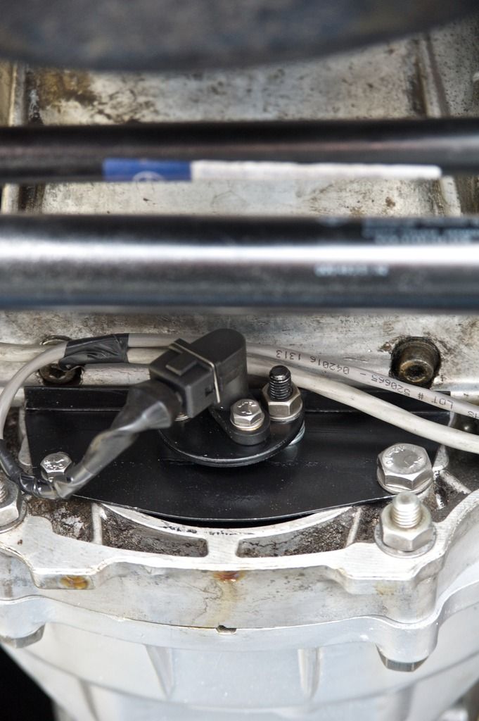
CPS now wired in (using shielded cable as per the lambda sensor, loom of both visible)

W114%20cps_zpsdfctipdo.jpg


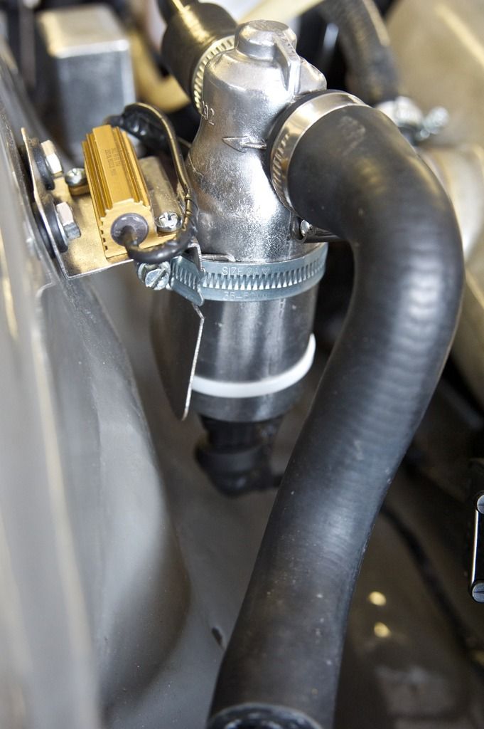
Idle control valve wired in and tested (motor inside turns both ways - the gold thing visible is the 50W 25ohm resistor to earth)

W114%20iacv_zpssadvev3p.jpg


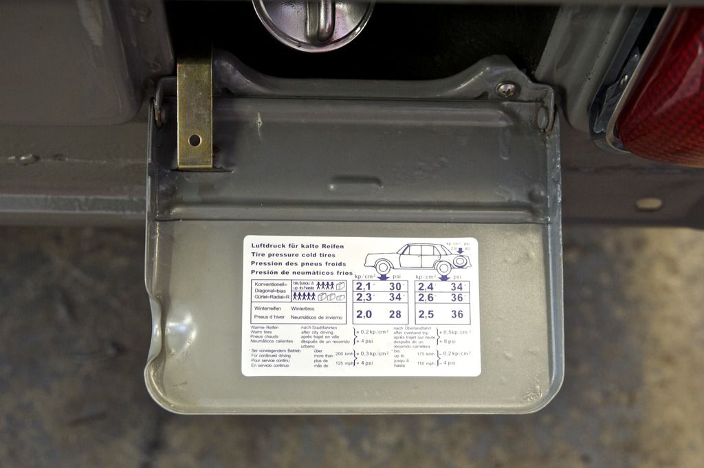
Minor details are taking shape too

W114%20petrol%20cap_zpsm59nrj1i.jpg


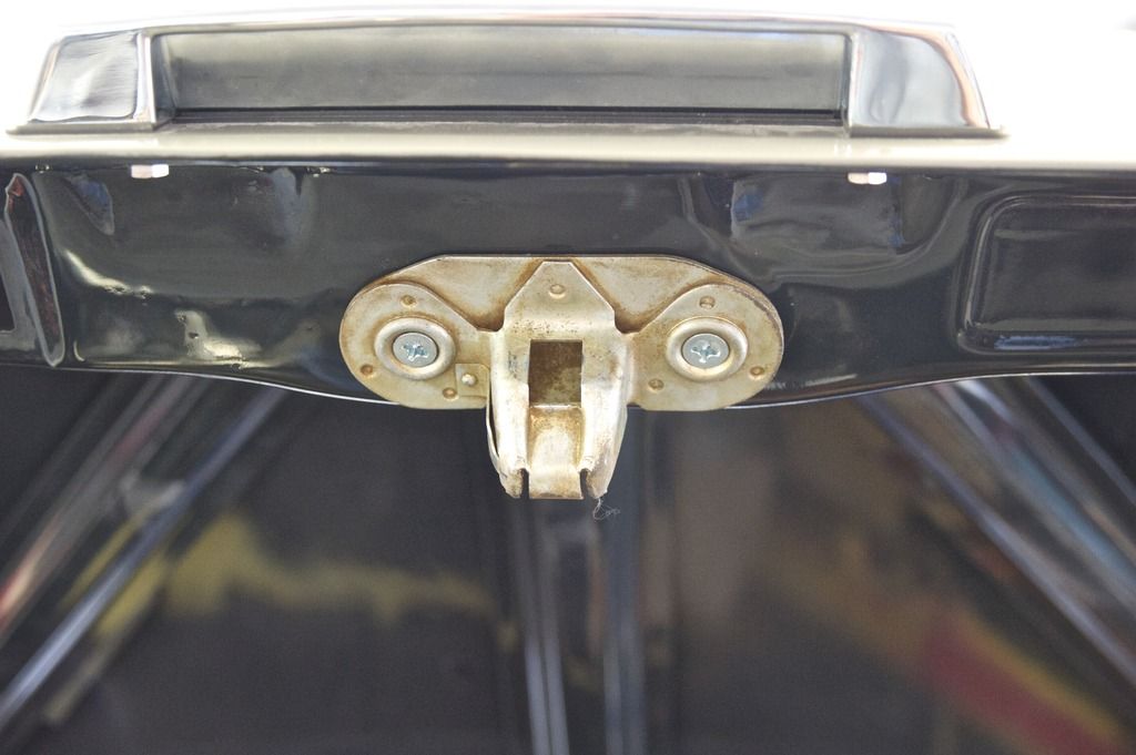
Yes, the bootlid now shuts and locks. DIY passivation possibly could have been better!

W114%20boot%20lock_zpspsx5mapi.jpg


But the big news today, we powered the ECU and lights flashed. The fuel pump relay was triggered and switched off when no CPS signal was found (need to calibrate in all the sensors). So we know it's functioning.

Just waiting for some suppressing HT cable to complete the spark plug wiring. Back there on Wednesday. My dedicated Windows laptop arrived today, so that will run Tuner Studio.
 

Users who are viewing this thread

Back
Top Bottom