• The Forums are now open to new registrations, adverts are also being de-tuned.

Mercedes W114 250 Coupe - help!

That sort of bad.

I'm assuming it will need an unleaded conversion - Tony's had it for 20 years and it had been off the road some time before then.

The list of things is stacking up.
 
Stripped both headlights which was a real task. The main reflector on each is held on by two long thin bolts into two nuts on each side of the dish which also act as the beam adjusters (you learn a lot when stripping things!). The bolts revolve within the metal casing of the headlight so adjusting moves the dish rather than the bolt so it is essential to avoid damaging them. The nuts were rusted on - for two the initial soaking with WD40 was sufficient, but the other two were buggers - the torque applied simply twists the bolts over rather than moving the nuts, and the shape of the unit made getting them in a vice very difficult.

All done now with only one bolt philips head a bit deformed. The indicator reflector is plastic and largely fine but the sidelight reflectors were rusty. Cleaned those off, kurust and then Zinc primer twice. I have a collection of old Halfords paints for all the cars I've had - these will be done in Citroen Black as it is a solid coat paint. The silvering will be replaced by vinyl silver tape that is used for car stripes - it should therefore last well as the interior of the lenses seem to get a lot of moisture and dirt in. As the sidelights are next to useless anyway, I doubt the loss of bright silvering will make any serious difference!

Both sidelight lenses and indicator lenses need to be put under some pressure to click them out of the frame - both have cracks already and with age didn't take kindly to being moved, so new ones have been ordered.

Total parts to renovate the units £88 inc postage. This is considerably cheaper than buying replacements!

As the rubber seals between the lens and the headlight frame clearly don't work, I'm toying with sealing the units with silicon sealant to prevent as much as possible future muck getting in. That is easily removable if required.

PS - if people have alternative suggestions as to how best to do things shout, I'm all ears.
 
Last edited:
PS - if people have alternative suggestions as to how best to do things shout, I'm all ears.


All done now with only one bolt philips head a bit deformed.

If you find the driver slipping on the head of a Philips head screw - apply a dab of grinding paste.

Some swear that Diesel and paraffin mixed 50:50 works better than WD40 as a penetrant/releasant. Never tried it but I don't rate WD40 highly.
 
My neighbour suggested a penetrating oil alternative which he had, but has gone away and I wanted to get this done. Some patience on my part required!

When I spent a summer working in the forge at Gibraltar dockyard they used a lot of diesel for cleaning things. It got everywhere.
 
My neighbour suggested a penetrating oil alternative which he had, but has gone away and I wanted to get this done. Some patience on my part required!

The best one in my opinion costs £140 for 12 cans (though an 18.9 litre drum can be had for £225). Not cheap, but if it spares expensive parts getting broken...

Away from that one, PlusGas, Diesel/paraffin mix - anything but WD40!
 
I promise not to use WD40

What is the name of this wondrous unguent made from the tears of Unicorns?


The best one in my opinion costs £140 for 12 cans (though an 18.9 litre drum can be had for £225). Not cheap, but if it spares expensive parts getting broken...

Away from that one, PlusGas, Diesel/paraffin mix - anything but WD40!
 
Just like the idea these early analogue systems can be tinkered with or improved to keep these old cars running. This is the definitive site for the D system ECU electronics. actual discrete electronic components hardly a chip in sight --who'd have thought. The waveform analysis is way above my head but the pictures are nice.

Those circuit boards are amazing. Lots of fresh air in there - compared with anything modern it's incredibly simple, but the process to get it that simple would have taken years of work

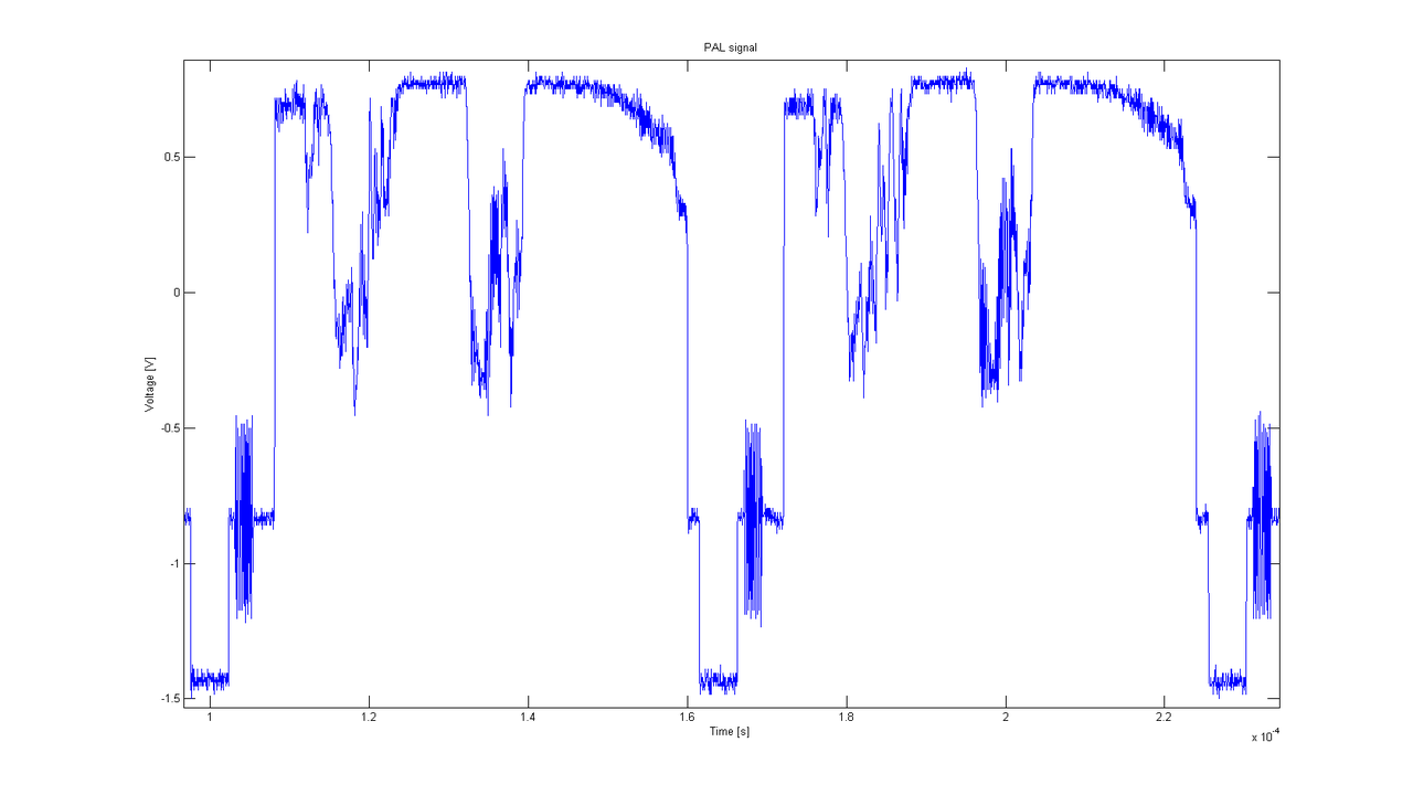
The waveforms remind me of analogue TV waveforms - each cycle of a TV picture (625 lines, interlaced, 25 frames / second) has a "front porch" and a "back porch" to allow the receiving set to synchronise, and a burst of signal in between which is the luminance (brightness) information for one cycle

The data needed for an injection (and/or ignition) pulse will result in a similar cyclic waveform but the frequency of the signal will vary with revs. Rather than governing brightness it'll govern injector duration. Just like a TV picture, the engine will need timing information so it can generate pulses at the correct point in the cycle. The crank position sensor generates the timing signal. There is usually a missing tooth in the timing wheel which generates a longer pulse, telling the system where in the cycle it is. This is the equivalent of the front porch in a TV signal

There were some very clever guys working in this field. When colour TV came about there was a requirement to make it backward-compatible with existing monochrome receivers. This meant not disturbing the transmission system or signal waveform - so the colour burst (the chrominance information) was dropped into the front porch where it is ignored by mono TVs

You can see the front porch in this image, with the short colour burst, luminance then back porch, twice over. This is two cycles, or one frame of a PAL system, plus a little bit

1280px-PAL_2_lines.png


It wouldn't surprise me at all if there were a few ex-broadcast engineers at Bosch cooking up all this stuff…

Nick Froome
 
Last edited:
Pretty much the same era as colour telly too.

I've found the original SM ECU (replaced by another before that was slung out for the Megasquirt). Given we are talking transistors I doubt it could be hugely difficult (but time consuming) to refurbish one if you know what you are doing.
 
I promise not to use WD40

What is the name of this wondrous unguent made from the tears of Unicorns?

Charles,

In my experience this stuff is excellent, although not cheap (£20/500ml) -

Industrial Lubrication with PTFE | Tri-Flow - Professional painting tools

Check your local engineering suppliers for availability..

Cheers,

Gaz.

PS Nick, that looks unterminated - should be 1V pk-pk and sync at -0.3.. 75 ohms will sort it ;).
 
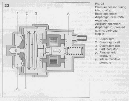
What I liked was the marriage of the mechanical and electronic via the MPS sensor. Altho the cross sectional diagram of the MPS I posted doesn't really help give the whole picture.
manifo2.jpg

The underlying principle of the linear variable transformer which is an integral part of the MPS is perhaps easier to understand via this diagram

34.jpg


in which a signal in the primary coil is induced in the secondary coil in a way that reflects the position of a moveable core.

The MPS measures the engine load by sensing the manifold pressure. In modern systems based on FI manifold pressure, pressure measurement is Performed by inexpensive, simple, and reliable solid-state sensors. At the time of the development of the D-Jetronic system (mid-1960's), "dry" sensors were nearly 30 years in the future. Precision electrical pressure sensors of the time were based on Linear Variable Transformer (LVT). The LVT used in the MPS is a very reliable device - failures of the MPS; generally are due a mechanical failures of the aneroid cells[ under vacuum when manufactured ] and diaphragm in the unit, largely due to metal fatigue. Essentially LVT's offer infinite resolution, fast linear response, and resistance in a harsh environment. Today's solid state sensors offer most of the same advantages but are are tougher and simpler to interface into electronic systems like the Megasquirt.

[The standard method used with an LVT for displacement measurements and apply is a reference sine wave to the input and measure the amplitude of the sine wave output, Which Varies linearly with displacement across most of the range of the device.]

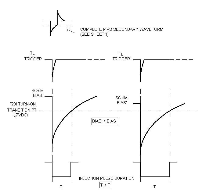
Bosch, however, did not use this standard method. Instead, a pressure-sensing circuit loop directs a current through the primary coil which decays at a rate dependent on the armature position, and correspondingly by, the manifold pressure. The induced current in the secondary holds the output of the circuit on until the current decays below a threshold value, generating the basic injection pulse.

Here are the waveforms and illustrates how the increased primary decay due to the mechanical armature displacement via the aneroid cell deflection induced by manifold vacuum depression widens the fuel injection pulse.

SCIM.gif


1.Basic injection pulse output of the PL - ground is 1 div down from the top
2.MPS secondary waveform - ground is 4 div down from the top
3. TL trigger waveform - ground is 6 div down from the top

PL01.JPG


Clever thing is they also incorporated the inlet air temperature sensor resistance in the circuitry since this compensated for any change in charge air density.
Explanation mainly from Paul B. Anders excellent treatise on the Porsche D-jetronic system.:thumb:


I'm going to have a lie down now.;)
 
Stripped both headlights which was a real task. The main reflector on each is held on by two long thin bolts into two nuts on each side of the dish which also act as the beam adjusters (you learn a lot when stripping things!). The bolts revolve within the metal casing of the headlight so adjusting moves the dish rather than the bolt so it is essential to avoid damaging them. The nuts were rusted on - for two the initial soaking with WD40 was sufficient, but the other two were buggers - the torque applied simply twists the bolts over rather than moving the nuts, and the shape of the unit made getting them in a vice very difficult.

All done now with only one bolt philips head a bit deformed. The indicator reflector is plastic and largely fine but the sidelight reflectors were rusty. Cleaned those off, kurust and then Zinc primer twice. I have a collection of old Halfords paints for all the cars I've had - these will be done in Citroen Black as it is a solid coat paint. The silvering will be replaced by vinyl silver tape that is used for car stripes - it should therefore last well as the interior of the lenses seem to get a lot of moisture and dirt in. As the sidelights are next to useless anyway, I doubt the loss of bright silvering will make any serious difference!

Both sidelight lenses and indicator lenses need to be put under some pressure to click them out of the frame - both have cracks already and with age didn't take kindly to being moved, so new ones have been ordered.

Total parts to renovate the units £88 inc postage. This is considerably cheaper than buying replacements!

As the rubber seals between the lens and the headlight frame clearly don't work, I'm toying with sealing the units with silicon sealant to prevent as much as possible future muck getting in. That is easily removable if required.

PS - if people have alternative suggestions as to how best to do things shout, I'm all ears.

Charles , when you talk about sidelight reflectors , the sidelights in these cars are within the main headlamp bowls ( the middle part of the lamp units ) using a small 5W side lamp in beside the headlamp , be it H4 or tungsten , with the indicators at the top and the fog lamps in the separate bottom section ) .
 
Twas rumoured that the headlight lenses on the /8 W114/W115 cars were the last to employ Mercedes "sideways illumination" principle where stray light from the headlight lens was designed to illuminate the grill and bonnet star at night. Whether this was true or not or its one of those urban legends I don't know but makes a nice story?
Capture.jpg
 
What I liked was the marriage of the mechanical and electronic via the MPS sensor.

That's beautiful. It's effectively a mechanical Wheatstone Bridge

Great ingenuity to combine mechanical, magnetic, analogue and digital electronic technologies

Nick Froome
 
Just came across this thread yesterday. Lovely story.

Good luck Charles, you definitely need to heat your garage now!!
 
Twas rumoured that the headlight lenses on the /8 W114/W115 cars were the last to employ Mercedes "sideways illumination" principle where stray light from the headlight lens was designed to illuminate the grill and bonnet star at night. Whether this was true or not or its one of those urban legends I don't know but makes a nice story?
Capture.jpg

I don't recall it with my 114 or 115 , but certainly the lights on my W111 did scatter sideways due to the bulging of those 'Lichtenheiten' glass lenses :)

 
I think the lenses are just too flat on the 114, but it's a nice idea.

I'll start sorting the large chrome bits tomorrow. Given the weight and shape of the bumpers I'm not sure my plan to store them in the garage rafters will survive its first clash with reality but lets see.
 
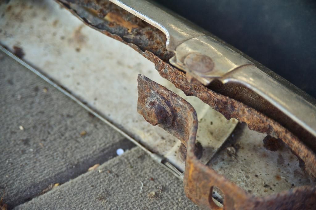
The next challenge - removing the heavily corroded rear bumper cross-member.

rearbumper_zpse91f2f17.jpg
 

Users who are viewing this thread

Back
Top Bottom