W215 Battery Drain

Page may contain affiliate links. Please see terms for details.
Dash 1 I am following the thread as an interested outsider.
I note you say all MB alarms are susceptible to damage from battery leakage when the batteries are older. Would you recommend that batteries should be changed when they are say 6 or 7 years old and is it an easy job to replace them. I am surprised it is not a specified item in the service schedules.
I admire your knowledge and the time you are devoting to this topic.


Hello KjI,

Thank you for the question and to digress slightly off-topic for a moment. To answer the question correctly, then the answer has to be no, these units are sealed for life and as such are a disposable unit which means following its life cycle (approx 8 years or so) its meant to be replaced. MB has no such provision or inclusions within the servicing regime to cater for such a product, which would include invasive repairs. It’s like everything else, when it fails then its time to replace it.

However, that does not mean to say that it can’t be repaired, on the contrary, because it can. Again, this would require that you would actually have to physically cut the unit open around its base and then find some way of resealing it following replacement of the batteries. Even when you open it up, who’s to say it’s actually then worth repairing

These batteries are available to buy, but the cost implications (approx £25.00 per unit x 2 units) and the hours in carrying out such a repair are uneconomical in the circumstances. There are two banks of batteries each containing 3 x 1.2 volt button cells, which make up the voltage to 3.6 volts – Total voltage is therefore 7.2 volts. Have a look at the photos I have just downloaded from the Internet to give you some idea as to the damaged caused by the deterioration and leakage over time. From memory, and I stand to be corrected on this, but the alarm units from MB are about £115.00 including the Vat.

Hope the info was of some use to answer your question.

Best Regards,

[FONT=&quot]Dash1


[/FONT]
 

Attachments

  • 1.jpg
    1.jpg
    117.4 KB · Views: 26
  • 2.JPG
    2.JPG
    206.5 KB · Views: 24
  • 3.jpg
    3.jpg
    109 KB · Views: 23
Thanks for the info. Very informative as usual. I thought it would be just like changing the CMOS battery on a computer, but as usual with today's products built in obsolescence.
 
So after going through the post by Dash1 in detail I can provide the following update.

Regarding the battery drain I only began to notice it in the last 2months or so - previous to this and when I am not driving the car I have it on a CKET battery charger so the drain could have been there a while.

Yes Dash1 I did what you have suggested on the AAC instruments panel and that was the only fault to come up even when I scrolled through. To be honest I am not sure how long the light had been on and I just noticed it when I went out to do the checks you suggested. I cleared the fault code and it initially did not come back on. I started the car and the light came back on after about 1min. I did the fault code erase again and it never came back on since (this was on Wednesday) - probably started the car on 4 different occasions since this. I will still get the refrigeration pressures checked and the system re-charged when I leave it with MB.

I am getting to grips with the multimeter now Dash1 it is the first time I have ever really used one so just took a while getting use to the various items on it. At least I now know to start on the 10amp reading and adjust as necessary. I have done the check again but with this time doing as you have noted with the boot catch locked - previously I had been leaving this open.

So with everything closed (boot open but latch closed) I hooked up the multimeter and set it at the 10amp reading and monitored this for an hour. The boot latch closed seemed to have made a massive difference in the outputs I have now got in comparison to my previous test.

· In the first 10mins it went between 0.22amps to 0.15amps with this fluctuating between these figures for this time period

· After this it began to fluctuate between 0.09amps and 0.10amps for a 15mins period.

· the amp reading dropped after 25mins to fluctuate between 0.06amps and 0.07 amps. the reading would sit at this for maybe 1min or so but then a quick jump to 0.11amps and 0.08amps would happen and then dropping back to 0.06amps and 0.07 quite quickly again. This repeated over the remainder of the hour.

Just to be sure I did this again later that day and I got the same outputs as above.

I also just thought that when I was doing this that I would see what happens if I leave everything shut (boot open with latch closed) and just lock the car with the blade key. In this arrangement I believe the alarm system is not engaged. After a period of time I got readings of 0.03amp/0.04amps with this fluctuating to 0.10amps/0.11amps for the remainder of the time I left it on which was approximately 30mins.

In relation to the locations of the SAM control modules is there a diagram/information to the location of them on these cars? just from all we have went through there appears to be a few of them.

Dash1 as soon as you mentioned re-synchronisation I just remembered that is what I was supposed to do in relation to the windows etc as this had happened to me before. All the additional information you provided in relation to how the back windows operate is very good for me and all other CL owners to know. Thanks I am learning by each post you put up!
 
Hi Ray,

Thanks for the update and the additional information. I really am extremely sorry for the delay in coming back to you as I know how important this is for you to get the car repaired, but as you know most of my time these days really is accounted for with work commitments, roll on the end of July, I’m actually counting the days down now and not the months. This is going to be a long post Ray, so hopefully I am going to try and put everything in to perspective and cover all that you will need to know and do. I would suggest that you cut and paste this on to a word document and then print it off so you can refer to it later on when on the car.

Before you do anything on the car though, read over this post several times so you can familiarise yourself with the context of exactly what I am saying and in particular when you do come to use your multimeter, its important that you give me the correct data. I will guide you through the process of using the multimeter on what to select, the appropriate range and scale as and when we come to check the car later on. If you wish, you can also still use the other ammeter that you bought and place that in series with the battery and the battery lead if you make up a couple of small jump leads, you can also use it for final clarification once we have found the issue, hopefully, at the end of all this you will have found it and its causation.

I have noted what you have said in your last post and this is encouraging news and not as bad as originally thought. When you refer to the present current drain fluctuations, they are still far too high and inconsistent and there does still appear to be an issue here. The only ones that appear to be in the acceptable range limits are the 0.030 to 0.040 amperage range, which is consistent with what they should be in a stable condition. The modules on your car should have shut down completely within the hour and should not have taken any longer than that. In one of my earlier posts, if you look back at it, I specifically mentioned the fact that some modules, although they do go in to “sleep” mode, do have a tendency to awaken again, these are by far the most difficult issues that anyone could have when trying to diagnose any form of parasitic drains. We refer to it as a “phantom” drain, and as the name implies, they do come and go and no reasonable explanation at first as to why, on that basis, the systems needs to be investigated and the problem is that we need to find it when it’s present to identify the module, or indeed if it is a module. The engineering term by the way is correctly named as MPPD’s (module parasitic phantom drains).

Normally, I don’t ever get involved with this type of work anymore, but under similar circumstances, I would generally have just put my own laptop on a vehicle so I could closely monitor the active/inactive status of every module on the car. I’ll briefly explain, when a module goes in to “sleep” mode, each and every module is then given a status of zero, zero meaning off as in “sleep” and the time is recorded and is monitored over a period of time, if, for example, a module awakens, this is denoted by a number one status, the time is recorded again until it then goes back to sleep, if indeed it does go back to sleep, this is then recorded and denoted as a number two status and again the time is recorded. This process continues over many many hours, sometimes over a 24-hour period and covers every module on the car and can only be done under certain conditions. Its not practical or even possible for us to watch the car for such a long period, but what we would do is to leave a laptop connected which will in fact do the work for us.

Its equally fair to say that some modules are specifically designed and programmed to awaken to monitor the system actually under its control, pretty much like your own PC at home would do if you have a calendar with a specific reminder date, an example on a car would be that of an active air suspension system, where the height and attitude of the vehicle is monitored and evaluated through its various strategically placed sensors. However, in the real world, such as your problem at the moment, its not always possible or practical to replicate that scenario, so we adopt another approach but as with any type of vehicle diagnostics, especially electrically related, these need to be visually monitored with the use of electrical test equipment such as an ammeter, lab scope, etc., as you don’t have laptop or the software at your disposal to do this.

There are many ways in which one can carry out parasitic drains tests, to which I have only named a few on an earlier post which are the most widely accepted and used in the motor repair industry, some are relevant and others are not, some are more accurate than others. What we tend to do is to be less invasive in opening up a circuit if it can be avoided. Even when you do open a circuit up, there is always the possibility that something adverse can go wrong, modern motorcar electronics are very susceptible to voltage surges and as such can in fact damage sensitive electronic circuitry. I’ll cover and guide you through a test later and you will always find it very useful and easy to do without subjecting the car to any risk of damaging any of the electronic components, although it would be equally fair to say that there is no such thing as being 100% risk free when working with electronics, but this test is in that regard is a non-invasive test and we don’t actually need to open a circuit up to insert an ammeter to measure the quantity of any parasitic drain, we evaluate this through the voltage dropped across the circuit/s.

With the greatest respect here Ray, the last thing you should ever be doing is pulling fuses and relays out from circuits that are actively live, this really is bad practice and not one that I would normally advocate or endorse unless it was absolutely essential and necessary, which may very well be the case if some test methods don’t produce the results. Unfortunately, this method of approach has long been established and practised in the absence of not having the equipment to test the circuit fuse and it would be extremely difficult to convince people otherwise now.

There is no need to pull fuses out if you understand how to use a multimeter properly and you are familiar with the circuits under test. A very simple millivolt drop test over a fuse is sufficient enough for us to qualify and quantify its electrical integrity if current is actually flowing in that circuit and the amount of current present. Yes, there are calculations to be done here but this is beneficial and certainly outweighs and avoids causing any issues. Most people just pull fuses at random and are not aware of any potential consequences, and why should they be; they are not trained in vehicle mechanics or electronics, so they do what they have always done and what they read and learn about from the Internet.

You would be surprised at the amount of damage one can actually do by just pulling fuses out of circuits unnecessarily. If you read my earlier post, (and I am certainly not being critical of you here Ray) you will see that I asked you to wait whilst we monitor the circuits first and I did that for a very good reason. I’ll ask a question of my own here, would someone deliberately pull the plug out of their home PC when it was switched on, the answer I would expect them to say would be no, then why on earth would someone do it on their motorcar, its no different. To remove a fuse from a circuit with current flowing will only exacerbate the problem, most people don’t know that when the fuse is reinserted the module boots back up, just like a PC would and starts the process of at the beginning again, only in our case, this just adds addition current back in to the system that we are tying to monitor for excess parasitic current, it really doesn’t make any sense to me at all, and yet, I see people do this on a regular basis.

There are occasions when it is absolutely necessary to remove fuses or relays, an example of this would be the fuse removal on the PSE module, to reset this module, following the time out facility, that’s exactly what should be done and it should be disconnected from its power source so it will lose its short-term memory and start the process off again at the beginning. These modern motorcars today are not like they were 25 or so years ago, and when something goes wrong they are extremely expensive to repair. Believe it or not Ray, but you do really have one of the most advanced and complicated motorcars that Mercedes Benz has ever built, and I kid you not when I say that, the amount of electronics and equipment on your car is phenomenal and when dealing with them one has to be extremely careful.

Ray, I don’t like to ask you the question here, but I am going to ask the most obvious question that I get asked on so many occasions and the answer I give to them still applies here. Have you actually checked over the car to see if anything has been left on, no matter how insignificant or trivial you may consider it to be? Things such as vanity mirror lamps, door exit lamps, centre console lamp, yes there is a light in there on the CL’s, even down to the cigarette lighter element being detached from its housing and sitting in the bottom touching the electrical contacts, they may all sound really silly and trivial things to check, but in reality it really does matter, this is a common sense approach before considering anything else as often it usually is something quite simple.

Has the vehicle ever had anything else fitted since you bought it Ray, such as a tracking system device, phone or anything of that nature? The only reason I ask these questions is that the parasitic drain now appears to be quite low in comparison to what you had initially, which was 2.4 amps, (2.400 milliamps) which to me would now indicate that whatever is drawing the current at the moment is consuming approx 0.060 amps over and above what we are expecting to find as a normal acceptable parasitic drain. A parasitic drain of 0.060 amps if measured across a standard 10 amp fuse would only represent a voltage drop of only 0.5 millivolts, which is half of one millivolt. If you are happy that everything possible has been done and checked on the car, then we can now start to look at the systems.

We can start anyway with checking if the vehicle has a short to ground first because this will form the basis as to where we can go from here. Start by removing both the battery leads off the battery, negative terminal first and then the positive lead. Leave the leads off the battery for about five minutes or so and then connect the leads together, keep them together for about a minute or so, I actually just use an elastic band for this purpose. The reason being is that we want all the capacitors to drain down, its not important for you to know why at the moment, but I will explain all that after we repair the car, but before we do the next test the system must be completely isolated of any form of voltage/current source.

With your multimeter, select the 20 ohms scale range only at the moment and place the test leads in the appropriate jack plugs, black to the common socket and the red in the volt/ohm/milliamps socket. There is no Delta zero facility on that meter Ray, so we will have to take that in to account when we do any calculations. Hold the multimeter test leads together first and then read off the ohms scale, on your meter it should be reading 00.1 - 00.2 or thereabouts, depending upon its accuracy. Whatever the reading is on yours, that figure is referred to as “above” Delta, so when we test any circuit we can deduct that figure from our final figure.

With the battery leads still disconnected from the car, put your multimeter leads across both the positive and negative battery leads. The reading you should get is a considerably high resistance value depending upon the specification of your car. Set your meter on the 200Kohms range scale first or higher if necessary and if you get a reading similar to the reading you got by just connecting the multimeter leads together, i.e., - 00.1 - 00.2 or thereabouts, then that indicates we have a short to ground somewhere, possibly an alternator diode fault or a relay may be stuck, in some cases, unfused circuits shorted to ground, it could be anywhere and on any circuit at the moment Ray.

If everything is OK up to this point, which I am pretty sure it will be given the amount of parasitic drain you have and a very high resistance reading over the battery leads, then make a note of it and let me know what it is so I can make some calculations later, now reconnect everything back together in the reverse order, positive lead connected to the battery first followed by the negative lead. It’s entirely up to you at this point if you wish to re-synchronise all the windows and sunroof again. Start the car and let it idle and just run through the general operation of the vehicles systems, lights, indicators, horn, etc. I am not convinced that you have any short circuits on balance because of the low drain but I am just checking every possibility here Ray and don’t want anything else to influence the readings we are about to get when we come to test the circuits.

The next tests Ray are extremely important, if not “the” most important and the voltage drop data recorded from your multimeter has to be accurate as there is a specific formula that I will have to calculate on your behalf based upon the test results obtained. The test is a completely non-invasive test, which means that no part of the circuit’s integrity has to be compromised here during the test. We can then go on to test the individual relay circuits after doing the volt drop test where we are measuring the millivolts dropped across each individual circuits fuse. If any readings are high, then I’ll convert them in to milliamp drains once we have a stable baseline figure of parasitic drain.

At the moment it appears to be very unstable with the fluctuations you referred to. I need to identify the total amount to give me some idea as what may be drawing such a high parasitic drain level. It’s not possible to do a millivolt drop test unless there is current actually flowing in a circuit, and if there is current flowing in a circuit, irrespective of what that current level may be, then that means that the circuit must it be switched on and is consuming power, which is what we now have to ascertain and this is probably where the problem will in fact be. There is a vast amount of circuitry on a W215, not to mention how many modules are on the car, in fact some modules are specifically known to failure, such as door modules, seat models, even the CD players have issues, something worth considering here Ray by removing the cassette pack from the CD player before you do any further parasitic tests. Even the wiring harnesses in to the doors from the cabin have major issues with mechanical breakages here on the CL’s, something which we may have to check upon later.

Before we do any tests, switch on the lights for several minutes to remove any surface voltage from the battery, let the readings settle down and then make a note of the battery voltage and also the resistance value from the test we did earlier on the battery leads. At the beginning of the post I suggested that it would have been advantageous to have two multimeres, if you haven’t got two Ray, then we will have to use the one. On your multimeter, you can now select the 200m millivolt range only, (we can scale up if necessary) and we can measure the voltage dropped over the fused circuits first, if any of them are active, then current will be flowing in that particular circuit which will give us a millivolt drop reading on your meter.

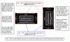
Do all the tests as outlined Ray on every single fuse that you can possibly gain access to. Do not remove any fuses at all until we find the culprit, if you look on the top of each bladed fuse, then you will see two very small holes that you can put your multimeter test leads across to measure the millivolt drop. Make sure you have a good contact on them with your meters leads, if need be, then lightly sharpen the meter probes to a point. Come back to me with any high figure results and I will calculate and convert them from millivolt drop values to milliamp drain values. Please take your time Ray in doing them; there is no rush and if necessary adjust your meter range to obtain the best possible value. I appreciate that all this is new to you and it will take up quite a bit of your time. When dealing with fluctuating parasitic draws that you have, then the only way to deal with them correctly is as I have outlined in the above unless you have a laptop to work with. Here is an example of what we are actually looking for Ray, which will give you a better guide and indication as to what is going on and what values to expect.

Example - I’ll use the circuit for the AAC system here Ray. When you do a millivolt drop test on fuse number 82, the millivolt drop that should be obtained should be less than 0.1 which is in fact a tenth of one millivolt and that figure alone actually represents a parasitic drain of 12 milliamps (0.012) across the fuse, which is still in excess of what it should be when that module alone is in sleep mode. This module when in sleep mode should only draw approx 4 milliamps, (0.004) which you would not be able to detect using the millivolt scale range on your multimeter, therefore, you should see and be reading absolutely zero on your multimetre in the millivolt range scale, if you see and monitor a reading of zero, then the circuit is functioning properly meaning that there is no current flowing which would be represented as a voltage dropped over the fuse when testing. That particular module is in sleep mode and the very low current drain of (0.004 amps) current being drawn is in compliance with its own parasitic limits. If you place an ammeter across the terminals in place of the fuse, then depending upon the accuracy of your ammeter, it will actually register in the very low milliamps scale range only.

To do all the tests that I have outlined properly, familiarise yourself here in the procedure in setting up the car prior to doing any tests, open the bonnet and press down on both the n/side and o/side bonnet locking catches, the alarm microswitch is also located here on the o/side catch if you wish to arm the car alarm later and add that in to the equation, open the boot lid and close the locking catch mechanism as previously noted, push in the door contact switches, the ones for the short stroke window operation, secure them in place Ray with some type of blunt object, open the drivers door and let the seat move right to its end travel position and leave it in that position until you have finished the testing, you will also need access to the n/side fuse box here so its best to do it now to save doing it later during the tests and finally, close the o/side and n/side door locking catches in to the locked positions, the same as you have done on the boot lid and then lock the door with the blade key. Its quite a lot to remember Ray but once this is done wait at least 45 minutes before you touch the car.

Now that you have done all that Ray, you have the freedom to move around the car unrestricted so you have full access to both the n/side and o/side front fuse boxes under the bonnet, the n/side fuse box at the side of the dash and the fuse box under the o/side rear seat. The last thing you want to be doing at this stage is introducing additional current flow in to the system when you are trying to find a parasitic drain, so doing all this beforehand is less likely to be an issue, especially if you have already inserted the ammeter in series with the battery. I am pretty confident that you will find this Ray if you do everything that I have stated, all that is needed is a common sense approach. It’s really just a matter of patience and unfortunately it takes as long as it takes. Diagnosing electrical issues can in fact be either straightforward and relatively easy to find, or it can test the most skilled individual at times when you have issues as you have at the moment. If all the above doesn’t reveal the identity of the fault, then its even easier when it comes to isolating individual relays and modules, but lets see where this takes us first Ray, we can only do so much at a time.

At the beginning of the post Ray I stated that at the end of it we should be in a better position to make some form of judgement and/or conclusion from all of what we have covered and gone through to date. The reality is this; we have established that we now have a figure of 0.060 milliamps drain over and above what we would like it to be which is 0.047 milliamps at its maximum. So lets consider this for a moment, if for example, that 0.060 milliamp drain was just on the one circuit alone, then we would expect to find a voltage dropped across that circuit of just under half a millivolt. However, that voltage drop and parasitic drain could very well be shared amongst several circuits, modules or anything else on the car come to that matter. When dealing with very small current drains such as this and nothing obvious comes to mind, this is where we have to be so precise with our measurements and these are very easy things to miss for an untrained person, and that comment certainly isn’t a criticism here Ray, on the contrary, I can’t commend you enough for taking on the task and challenge and its because of this very reason that I genuinely have afforded you my time and I will continue to do so until you are happy with the car. Also, what I think you will take away from all of this is the fact that you will see the distinct benefit of measuring the systems now by the volt drop method, not only that, but you have an advantage here over any type of measurement system available. You can measure the before and after voltage to actually see if a system has indeed been shut down and gone in to “sleep” mode.


Continued.......
[FONT=&quot][/FONT]
 
When you initially started to pull fuses out it didn’t prove anything other than to confirm there was a large current draw. Now that the figure of 2.4 amps (2,400 milliamps) has been reduced we have our final figure and by pulling fuses out at this stage would not give us an indication of where it is, this is why it is extremely important for us to measure accurately the voltage dropped over all the circuits and if that fails to materialise our figure, then we need to start looking at the relay controlled circuits followed my module elimination. Being such a tiny amount of parasitic drain, to find it on a Mercedes Benz CL could prove to be very challenging for anyone, myself included here Ray. Unfortunately, I can only give you my best advice whilst sat here in front of my own computer screen, I wish I could actually get a “hands-on” approach here Ray but as your not here in the UK that’s not possible. I am still confident that you will find it but it’s a matter of patience and determination.

To answer your last question Ray, the rear SAM control module is and forms part of the rear fusebox under the o/side rear passenger seat, it does separate from the fuse box if need be. The rear central electronics control module for the rear windows is in the same area only this module is attached to an alloy fabricated plate, which covers the rear SAM control module. The front door control modules form part of the switches on the n/side and o/side front doors up near the air vents. The AAC modules are under the dash and front centre console, which is not as easy to gain access to, and would require quite a bit of trim removal. The front SAM control modules are on the n/side and o/side under the bonnet and once again are incorporated within the fuseboxes. We haven’t covered anything other than these to date Ray.

With regards to the AAC issue, we can wait until you have had the system checked when your car goes in for service before we cover that area again, so hopefully its just either the pressure sensor or its requires the system recharging. We can still test the electronics on the pressure sensor if you wish to go ahead with that part of the circuit anyway.

Hopefully, this post serves two specific purposes here Ray, firstly, it gives you an insight and the opportunity to test certain parts of the car without actually doing any physical damage to it and most importantly, is gives you a better appreciation and understanding of how complex the car is and the systems on it. If there is anything that you don’t quite understand or need clarification on, then please come back to me before you do any testing. I hope all this information helps and good luck.

Best Regards,

[FONT=&quot]Dash1[/FONT]
 
Dash1

Thank you for this. I am going to have a good read over this (a few times!) and make sure everything is clear in my head before I start anything.....again I am amazed at your knowledge!! Ray
 
Hello Dash1

Hope you are enjoying your break. Again thanks for all your advice and information as I have learned a lot about the electronics in my car and also about the process of checking/testing.

I have gone through your post many times and have spent yesterday evening/night doing the tests you noted. When I got into doing this it didn't take as long as I initially thought even when I was taking my time.

Regarding the approach you noted with a laptop and software I take it that this would be specialised equipment or is it something that someone could buy? Would this sort of equipment be cost prohibitive for a novice like me and more aimed at someone who does this as their career? - it seems like a good system to have especially on a car with lots of electronics.

In relation to pulling out fuses your comments are noted and I will not be doing that again. It is just a normal thing you see people doing and we (people like me) just assume then it is ok for us to do........its like the blind leading the blind. I seen this approach in a number of videos online and that's why I did it in the first place (this was before I started getting your very informative posts).

Yes Dash1 I did a good check around the car a while back to make sure it was not something simple but just to be sure I give it a once over again and all seemed fine with nothing obvious left on. I note your point though that it could have been a simple item that had just been missed.

Nothing has been fitted to the car Dash1 in the time I had it and prior to that there doesn't appear to be anything fitted before I got it. I removed the cassette pack from the CD player as you have suggested.

I selected the 200 ohms scale on the multi meter (you noted 20 ohms scale but my multi meter does not have that so I was assuming you meant the 200 ohms scale). I got a reading of 00.2 for the above Delta figure.

I did the process of removing the battery lead in the order you noted and left it for over 5mins then I connected the leads together for over a 1min (it is actually a tight pull to get the leads to meet). The resistance readings over the battery leads eventually settled at 08.6 when set at the 200 kohms scale. After this I started the car and went through the general operation of the vehicles systems like you said.

Before I did the remaining tests I switched on the lights for several minutes as you noted and let the readings settle down - the battery voltage was 12.72 (prior to doing all of the above I had the car on the Cket trickle charger and I removed this before I commenced any of the above/below)
I selected the 200m millivolt range and began to carry out the test on each fuse. Prior to this I had the car set up as you outlined in your post and left if for 1 hour. I went around all the fuses once and then just to be sure I did it all again. Of all the fuses I checked the only ones that I got a reading for are as follows:

· Fuse 78 - 00.2
· Fuse 62 - 00.1

If needs be I can repeat the whole process again if you think this will be beneficial just in confirming the figures above. As noted I did go around the fuses twice and the above are what I got both times.

Dash1 I know how busy you can be so I am in no hurry waiting for a reply. Thanks again.
 
Hi Ray,

Thanks for the update. I will eventually get round to and cover all the points that you have raised in the last post and to date, however, I haven’t got time at the moment to go through every single issue with you in any significant detail, but the recent tests you’ve done have narrowed it down somewhat (excluding any other untested parts of the systems at the moment) on the two specific fused circuits you mentioned - fuse numbers 62 and 78. One of them appears to be slightly higher than what it should be anyway, but the other is way out of specification, but that really does depend upon the accuracy of your own multimeter here, see below.

Fuse No.78 - This part of the circuit Ray should be protected with a 7.5 amp - brown fuse and is the main circuit for the steering column module, electronic ignition switch module, engine management control module and the anti-theft alarm system. The figure you obtained here of 00.2 on fuse number 78 is actually well above what it should be. The figure of 00.2 millivolts actually represents a parasitic drain of 0.018 amps, which is in fact 18 milliamps, so that part of the circuit if your multimeter is accurate is consuming above what its parasitic drain should be from all the aforementioned modules. This circuit alone at its maximum should be no more than 00.1 millivolts, which equates to 0.009 amps. This isn’t a need for serious concern just at the moment, (have you fitted a brand new alarm system to the car or other here Ray) provided we can trace the remainder of the excessive parasitic drains. As I said in an earlier post, we need all the modules to account for a 0.047 amps total parasitic drain. Was the meter readings fluctuating between 00.1 and 00.2 or was it “fixed” at 00.2 with no fluctuations, if it was fluctuating between those two figures then we can divide the value equally for now and retest individual parts of that circuit later on for clarification.

Fuse No. 62 - This circuit is in fact the PSE (pneumatic system equipment) control module and the voltage supply is via the 20 amp - yellow fuse. Again, the figure you mentioned here of 00.1 millivolt drop on this circuit is higher than I would have anticipated and expected on that module alone, in fact, its nearly five times higher. A figure of 00.1 volt drop over a 20 amp fuse would represent a parasitic current drain of 0.030 amps, or 30 milliamps on its own. These figures, although at first glance appear relatively small in number themselves add to the “global” figure which makes a big difference when we are trying to narrow something down. Don’t get confused here Ray with the volt drop being different over different amperage rated fuses, most people can’t even comprehend the fact that fuses have a resistive value, irrespective of what that value may be, otherwise, you wouldn’t be able to measure the voltage dropped over them without current flowing in the circuit. Another extremely important factor and reason here why different rated fuses should never be inserted in to a circuit they were never designed to protect. I’ll explain all that in some depth at a later point Ray and demonstrate why it shouldn’t be done. Have a look at the examples here below to give you an idea as to how important accuracy really is when measuring voltage drop over fused circuits.

Example – If I have a 7.5 amp fuse in a circuit with a volt drop measurement across it of 00.1 millivolts, then the current flow is equal to 0.009 amps, if I have a voltage drop in the same circuit only this time it measures 00.3 millivolts, then that is equal to 0.027 amps and finally if I have a voltage drop of 00.5, which is equal to half a millivolt, then the current flow would be equal to 0.046 amps. Can you see the direct relationship here Ray, the higher the voltage dropped across a given circuit represents a much higher amount of current flowing within the circuit, every fuse type rating will represent a different voltage drop for the same current flow and that’s because of their relationship with its intrinsic resistance value. The point that I am trying to reinforce here Ray is the fact how important the measurements need to be. When we have resolved the issues on the car, I’ll show and demonstrate two unique tests that you will always remember when testing for parasitic drain and selecting fuse applications.

If you were to consider the above two sets of figures alone that you obtained from those two circuits, then totalled together they equate to 0.048 amps, which is the magical figure we are looking for, however, that’s excluding all other parasitic drains from the remainder of the modules and systems on the car, and there are quite a few on a CL65. Some modules only consume as little as 0.001 amps in “sleep” mode and others up to as much as 0.004 amps. I do hope you can see the relevance and the importance here Ray and that we are trying to isolate and eliminate what we can and where we can. We are getting there, slowly but surely, but as I said in my last post, patience and determination is the “key” factor here to resolving these types of issues, but unfortunately its time consuming. By the way, you have done really well here in getting those figures, it just goes to show that you have done the tests and checks properly as I suggested, especially if you have double checked them and come back with the same results.

For now though Ray, disconnect the battery negative lead and place the ammeter back in the circuit and then reconnect the battery lead. Leave fuse number 62 out of its fuse holder altogether at the moment as we don’t want it to influence the other parasitic drain, this could well be the one that is actually giving us the fluctuations in our final reading as mentioned in one of your posts. You don’t need to try and lock the car with the remote as it won’t lock with the PSE immobilised and power disconnected, lock it with the blade key and just let the system settle down and monitor the parasitic drain again from the boot area only to see if its more stable now than the last set of readings you obtained. It should be at least 0.030 amps, 30 milliamps less than it was previously.

Ray, do you have keyless-go on the car, this module indirectly communicates with the PSE module over the CAN bus via the EIS to implement the unlocking/locking and global closing, something that we may have to consider looking at later on, lets see what the new parasitic drain readings bring first. I’m away for a few days this week Ray as and from late this evening as my wife and I are taking a short break and I will only be back late on Thursday afternoon so I will come back on the forum sometime during Friday.

Best Regards,

Dash1
 
Hello Dash1

I hope you enjoyed your short break and got some relaxation time!

As I noted in previous posts I am happy to wait until whenever you have the time as I know how busy you can be and of course I wouldn't want you spending your time on this especially when you are having a few days of a break. I also appreciate (and I am sure many others on the forum) all the input and detailed information you are providing in finding the issue in my car and how hard and laborious it must be for you having to explain all this out step by step via a computer screen.

Regarding Fuse 78 I have not fitted a new alarm system or anything like this to the car - I have only replaced the alarm siren as we discussed previously. The reading was fixed at 00.2 for Fuse 78 with no fluctuations. I note your point on how important the measurements need to be as from your examples any slight variation in volt drop measurement has an impact on the amp calculation. On Fuse 62 the reading did stay at 00.1 for the majority of the time but there was some fluctuations to 00.0 every now and again.

Yes Dash1 my car has keyless-go but when I got the car the seller did not have the keyless-go keys just the normal key - so I have never used this function on the car (so don't know if it works or not).

I put the multi meter back in circuit with fuse 62 removed and just locked the driver door with the blade key and left the car for about an hour. The readings I got was not what I expected as we were hoping they would be down by at least 30 milliamps less than it was previously. After about an hour the readings was 0.03 but with fluctuations up to 0.08/0.09/0.10 still occurring approx every 10-15secs. So I am not too sure Dash1 do you think I should maybe run the tests I did previously for millivolt drop test again just to double check against my last readings? Thanks Ray
 
Hi Ray,

Thanks again for the update and thanks very much for asking about the short holiday break. We really did enjoy ourselves; it’s been a fantastic week and especially with the good weather and all, it’s been quite a while now since we both had any kind of break. Ray, if I do have any time then I will always go out of my way to try and help a friend or fellow forum member, as you already know, I do have very little spare time at the moment as my current job consumes most of it and I am away from home most weeks, some weekends I never get the opportunity to go home. I look at it this way, if my input in to the thread helps and contributes towards resolving the issue then that’s what its all about, plus, there is always the added bonus that you may very well have learnt something from it in the process which will always be useful and beneficial for you in the future, regardless of the make and model of car you own. From an engineering perspective only, then I don’t and never have looked at cars for what they are; they are just a series of mechanical and electrical engineered systems to me, regardless of what bodyshell covers them.

The alarm siren that you have recently replaced on the car (see previous photos on an earlier post) is actually a complete module unit and incorporates all the electronics for the antitheft protection of the vehicle. The alarm control module responds and interacts with other modules on the car regarding the locking/unlocking and sensing circuits. Fuse number 78 is still a bit of a concern here though and the alarm system is on that particular circuit, which is why I asked about it in the first instance and one of the modules, which we will be looking at amongst several other areas of the car. Fuse number 62 is generally not so much of a concern here at the moment as we can in fact leave that isolated for the time being during some of the checks and then reinstate it back in to the main system when you find the issue. Following on from any of your tests anyway, you can always reinstate the power by just inserting the 20 amp fuse back in there once the tests are complete so you can lock the car securely, I just didn’t want it to influence any of the other readings at the moment when you are taking any voltage measurements.

Very strange Ray how you have the keyless-go system fitted and yet the key and system isn’t responsive, the current key/s needs to be programmed to the vehicle. Ask the service department at MB when your car goes in for service although I think from memory it’s about £90.00 or so to have it programmed, but it can be done and probably should have been done by the previous owner if these are new keys. If you do have keyless-go anyway, then to check if its active or not, just touch the capacitive sensed door handle, it should come up in the instrument clusters multifunctional display as - “KEY NOT RECOGNISED”, check to see if it does display this message, the same message would also apply if you press the remote start switch on top of the gear selector anyway.

With regards to your final observations and comments, the voltage fluctuations are still far too high to leave unresolved, something is definitely consuming power and whatever it may be is significantly affecting your final parasitic readings. Sometimes it’s a case of catching it when it occurs, other times its not there and that’s the scenario which proves all that more difficult to detect. It would be equally fair to say that you may experience some minor milliamp fluctuations within one or two milliamps either way, but yours is still in excess of some 60 milliamps, even with fuse 62 now removed, so your original readings could have been in excess of the original figures you quoted. When you did the volt drop tests, although they showed no level of activity other than on fuse numbers 78 and 62, activity could still be occurring on any one of the other circuits that you weren’t actually monitoring at the time, it’s a very difficult scenario to be in really, but hopefully after this post we can rule certain things out and it may become much clearer as to where it actually is. Even a typical standard 4/5 pin relay coil consumes 0.175 amps on its own, so we can effectively rule out the relays, but we must still keep an open mind on the fact that we could very well have a module that refuses to go in to “sleep” mode.

Lets start with a new set of checks on some other parts of the vehicles systems to try and narrow it down even further. I’ll cover these on a step-by-step basis Ray so it will be very clear and easy to understand. Don’t deviate from them and do exactly what I suggest and in the sequence as laid out below. Write all the data down from each pin combination that you are testing and I’ll explain what they are if we record any fault issues.

CAN (Controller Area Network). I’ll explain a little bit and very briefly here about the CAN data bus, which will give you a clearer and better picture of it when you come to do the test later. The system tests here are to evaluate if the network is either active or inactive. We need to carry out two specific test sequences here to determine the voltage levels but without any module activity on the bus network and the second test sequence is that we need to establish the circuit’s integrity (no short to ground or other circuits) of the network and the resistance values from the networks termination resistors.

The CAN data bus in very simple layman’s terms is a pair of parallel wires, which are twisted around each other, (36 twists per metre of cable) running throughout the whole of the vehicle and terminated at either end of the two wire networks are two 120 ohm resistors and these resistors are also incorporated in to the system. The only components that are connected directly on to the bus network are the electronic control modules themselves. Other electrical components, such as the loads – actuators, sensors, motors, bulbs, switches are all wired only to the electronic control modules themselves and play no part whatsoever in the communication of one module to another, the modules themselves determine the operational characteristics and strategy of each and every component that it has direct control over. So in short, the CAN data bus networks are merely a means of data transfer for all modules that are active on the bus network which are constantly exchanging date and being updated with information in millisecond time frames.

As a general rule of thumb, depending upon the vehicle manufacturer, which still uses this type of data bus for on-board diagnostics and communications medium, the systems can be accessed via the OBD II connector from a systems analyser, such as MB’s Star diagnostic software, amongst other reputable software on the market, which interfaces with and uses a networked bus. The two wires of the bus network, which are referred to as CAN “high”, which is the “dominant” wire and the other is referred to as CAN “low” which is the “recessive” wire will have the same voltage values when the ignition switch is turned to the “off” position with the key removed. The voltage thresholds, which will be present if nothing is found wrong within the bus network system is 2.50 volts on each of the wires and a voltage drop difference of up to 0.020 volts (20 millivolts) when actually powered up on-line without module data transfer.

When a typical data message is placed on the bus network for communication purposes with a recipient module, then the CAN “high” wiring is at a much higher voltage level than that of the CAN “low” wire, for example, a typical value of 3.2 volts on the dominant wire and a typical value of 1.8 volts on the recessive wire, the total voltage is therefore 5 volts of which is paramount to its correct functionality. Each and every electronic control module will inevitably have its own reference identity coding, or, if you like, a specific known address that may and will respond to several CAN identification codes. If an electronic control unit is to communicate with another module, then it will need to know the CAN identity code of the recipient module, otherwise, no communication will occur and this often happens when a module has been corrupted for whatever reason, even a short within the circuit will corrupt a signal because the voltage level will be have been pulled down below its operational voltage.

To do the next tests Ray, we are going to have to test the integrity of the bus network through the diagnostic connector, which is found below the dash adjacent to the bonnet catch release lever. If you get a torch and have a look under the dash you will see a small plastic hinged flap on the far right of the lower dash, pull down on the hinged flap to reveal a 16 pin female connector plug – this is referred to as the OBD II connector but it is correctly named as an SAE J1962 connector, which was a standard protocol at the time. There are two rows of eight pins (not all cavities are occupied, it depends upon the manufacturer) and the pins we need to work on are pin number 6 and pin number 14, see attached photo below for reference purposes, these are the only two pins you will need to know about at the moment and the pins are directly adjacent to each other in the opposite and respective rows, third pins up from the bottom. The diagnostic connector is wired directly in to the systems gateway module on a Mercedes Benz, but not so much with other vehicle manufacturers, which in turn allows communication to take place with all the other bus networks and any respective modules on those networks.

With your multimeter, select the 20 volt scale only and place the appropriate test leads in the respective jack plugs on the meter. If you have a crocodile clip for your meter, then put it on the black multimerer lead and then connect that lead to a good known ground point on the car, the parking brake aluminium bracket will do whilst you are working here in the foot well area. With the ignition switch in the “off” position and the key removed, measure the voltage on both pin numbers 6 and 14, you should have 2.5 volts on each pin, be extremely careful here Ray that you don’t spread the pins apart when you touch the contacts in the connector plug. If you have got 2.50 volts, then you can either put the key in the ignition switch (please don’t turn the ignition on) or even turn the lights on whilst at the same time keeping the red multimeter lead on the diagnostic pin and observe the voltage drop, it should now come down and drop to 2.48 volts, (our 0.020 volt drop from my above comments) if it does, then keep your meter lead connected to the pin and either remove the key from the ignition switch or turn off the lights and after 15 seconds the voltage will now go back up to 2.50 volts. Let me know what they are and do the test on both pins numbers 6 and 14.

Before you disconnect the battery for the next test Ray, just start the car up and let it idle for a few minutes and then measure the battery charging voltage, it should be around the 14.00 volt threshold or thereabouts – the minimum is 13.60 volts up to as much as14.40 volts “off load”. Your car has a SMART charging alternator and circuitry on it Ray but that won’t come in to effect here at the moment as the temperature in the UK is well above what is should be activated at anyway. Example - When it’s extremely cold, zero or below, the alternator will charge at a rate of 15.20 volts for a specific period of time depending upon the ambient temperature recorded at the time and information received from various engine sensors which are being monitored by the engine managements ECM, this is calculated and a message is then sent over the LIN bus (local interconnect network) to the alternators electronic control module to regulate the output voltage. Also, this is another area you can test if necessary at a later time, if any of the diodes within the alternator are faulty, then current will flow to the ground circuit, but see how you go on first with the other tests before we go down that route.

Ray, turn everything off and then disconnect the battery lead from the negative side only, place it in a position so that there is no chance that it can come back into contact with the battery post until we’ve done the next test. With your multimeter, set the range to the 20 ohms scale only and then I want you to measure the resistance across the two pins in the diagnostic connector, to confirm here once again, they are pin numbers 6 and 14 – third pins up and adjacent to each other in their respective rows. Now that the system is electrically isolated, place both you multimerer leads across both pins at the same time (don’t let them touch together) and you should now read 60 ohms, give or take either side but it should not be any lower that 59.8 ohms and no higher than 60.2 ohms. Make a note of the values so we can evaluate them later.

The final check here Ray for now will be another parasitic drain test, before you do that though, remove fuse number 78 and also remove the navigation disc out of the comand head unit - the single slot, you can also leave fuse number 62 out so we can take those modules out of the equation and now see what the parasitic drain vales are. Set the car up as you have previously done so as to gain the best test results. If you want to, then by all means do your volt drop tests again over the fuses as this will do no harm and may very well reinforce your last voltage meter reading as factual. The only two fuses that are left on the car that you haven’t accessed at the moment are behind the boot trim on the n/side. The sound amplifier has a 20-amp yellow fuse in it and the TV module, if you have one on your car, has a 10 amp red fuse. If you wish, you can also do a volt drop test on these or you could actually remove these two fuses for this test and note the change in the parasitic drain.

Let me know how you go on Ray if you have the time to do them before the weekend is over. I am at home all day today anyway just pottering about if you need any clarification or further advice but I go back to work in the morning and there is no guarantee when I will be able to get back on to the forum, possibly next weekend now. Anyway, do as much as you can in testing and checking the systems as outlined above, but most of all, take your time and do them properly and I am pretty sure you will find the excess parasitic drain, speak to you soon.

Best Regards,

[FONT=&quot]Dash1


[/FONT]
 

Attachments

  • OBD - II Diagnostic Connector SAE J1962.gif
    OBD - II Diagnostic Connector SAE J1962.gif
    24.5 KB · Views: 32
Last edited:
Hello Dash1

Hope you are keeping well.

Apologies for the delay in responding to the thread - I just never got a chance until now to carry out the tests you noted. I got a few hours yesterday evening and got to carry out most of the tests - I still have to carry out the final parasitic drain test which means getting to the fuses of the TV module and sound amplifier which will require me to remove some of the equipment so I have left this for now until I know I will get a few hours at the car.

I firstly tested the voltage on Pins 6 and 14 separately as you noted. When I looked at the port it was actually a bit different than image you sent in that the numbering of the pins where the opposite way about (see photo). Each pint had a number so I could see Pins 6 and 14. The results I got are not what we expected so not sure if this indicates where the issue may be. Results are as follows:

Pin 6 = 2.43
Pin 14 = 2.43


When I switched on the lights the readings actually when up as opposed to down:

Pin 6 when lights switch on = 2.47
Pin 14 when lights switch on = 2.47

When I switch the lights off the reading settled back down to 2.43 after a short period. Just to be sure I did this again and instead of switching on the lights I put the key in the ignition and I got the same results as above i.e. 2.47 for both Pins 6 and 14.

Before I carried out the next test I started the car and let it idle for a few minutes and then checked the battery charging voltage which was 14.06.

For the next test I disconnected the negative battery lead and then checked the resistance across Pins 6 and 14 and I got 60.4.

Thanks


Hi Ray,

I’ve just read your last post and I am going to read through the whole of the thread again later on tonight to see where we are up to. I haven’t been on here for quite a few weeks now to I’ll catch up on what I’ve already stated and covered. I probably won’t come back on today but I am home all day tomorrow so I will put something together and cover all the points that you raised. Don’t worry, as there is nothing in your last post to warrant any concerns.

Speak to you sometime tomorrow.

Best Regards,

[FONT=&quot]Dash1[/FONT]
 
Hi Ray,

I did leave you an earlier message on the thread on Saturday evening to say that I would reply sometime yesterday, unfortunately, I didn’t really have the time so my apologies for the late delay. Anyway, thanks for the update and yes I am doing really well at the moment, fingers crossed, so thank you for asking. I can’t yet get my head around the fact that I officially retire from full time employment on Friday; I still have very strange and mixed feelings about it at the moment. You don’t need to apologise for anything Ray, I am very much like yourself really and I don’t seem to get the time to do most things I want to do these days anyway, hopefully, all that will change from the end of this week.

Firstly, there is not an initial problem to be concerned with here Ray, on the contrary, what you have just checked and confirmed here is the bus systems electrical integrity through the OBD II diagnostic connector - J1962. The connector, as previously stated in my last post, is “hard wired” directly in to the vehicles systems central gateway communications module, sometimes referred to as an applications gateway because of its functionalities and interactions with various CAN buses and other networks. Prior to the end of 2002, Mercedes Benz communication networks went through the EIS (Electronic Ignition Switch) and from 2002 on the vehicles electrical architecture now incorporates the main systems central gateway module which is located under the dash on the CL’s, its about the same size as the navigation unit in the boot of your car and its powered up directly from circuit 30 (which is a permanent live circuit) via fuse number 83, which is a 10 amp fuse.

Ray, to save any confusion here, there are 5 different networked buses on the CL and all of which are unique in themselves and operate on different voltage levels as well as an optical level of which I will briefly identify as we go through. The networked bus that you have just tested the system through is referred to as CAN bus “D”, which is a high-speed diagnostic bus of which is a low voltage (5 volts) bi-directional twisted pair which communicates with all other modules on the car. All of the vehicles bus networks are generally accessed and communicate through the central gateway anyway which gives us the ability to carry out certain manual checks and tests without the use of any specialist diagnostic equipment, there are many other ways in which we can do this, but these would be very time consuming and involve removing a considerable amount of the vehicles interior trim to gain access and I am trying to keep this as simple as is possible with equally similar output test results.

The two main primary bus systems on the car are the CAN bus “B”, (medium-speed bus for body functionality) which is for the lights, doors, seats and instrumentation etc. and CAN bus “C” (high-speed chassis functionality) which is for the powertrain, transmission, anti-lock brakes etc. There is a local bus system, which we refer to as the LIN bus, (lower than medium speed – which is a local interconnect network) which is primarily, depending upon the vehicle manufacturer, anything between an 8 -12 volt operating range on a single wired bi-directional circuit which is mainly used for communication with the alternator and the ACC module for the servomotors, amongst several other sub-system minor circuits. The audio and telecommunications bus network on your CL uses an optical system, which is referred to as MOST, (Media Orientated Systems Transport) which is based upon the well-proven POF technology, plastic optical fibres. Earlier systems on the CL’s prior to MOST were the D2B network, which is again an optical cable, its not pure fibre optics as such as people often imply, pure glass fibre optics would not survive the harsh environment within the automotive car manufacturing world, they are far too brittle and plastic polymers are much more preferred because of their cost, flexibility and immunity to any EMC - Electromagnetic Compatibility.

The CAN bus wiring termination connectors on the CL’s run parallel along both inner front sills under the floor carpet and a further one is located under the lower steering column above the footbrake pedal. In any age related circuit anyway, we can and always will find minor inaccuracies even though your figures are only 0.010 and 0.070 millivolts out of specification during the tests. I’ll explain the theory behind that but even on a ground circuit we would allow for a 0.1 volt drop, which has little of no effect on the circuits under test, the lower the figure the better which always provides for an unrestricted current flow. Any resistance found in any circuit is always unwelcome, unless, that particular circuit is specifically designed to incorporate such a resistive path, which the CAN bus is and for a very good reason which I will describe shortly

There are two termination resistors located within the CAN bus system and they are there for a very special and precise reason, the CAN bus must be terminated at both ends of the network by a single fixed 120 ohm precision resistor to match that of the circuits own electrical impedance and these resistors are placed across both ends of the CAN high and CAN low circuits so that reflections of any electrical signals are avoided, electrical interference and anomalies in these circuits could prove disastrous. The majority (excluding shorts/opens to ground or other circuits) if not all of the problems in a CAN bus are usually caused by improper connections, poor termination, wrong bit rate selection or module identification/configuration. The figure you quoted here Ray of 60.4 ohms is pretty much within specification, which gives us an indication that the circuits integrity is as it should be, but there is always the possibility that the slightly higher figure than I quoted would have resulted from such a corroded connection/condition due to the age of the car. Did you actually take in to account the delta zero tolerance of the meter Ray before you considered the value obtained, if not, then the reading you obtained would have been accurate to what I stated. This is something that we could look at later on once we resolve the excess parasitic draw issue. This 0.2 ohms differential figure wont affect the operation of the bus data messaging anyway unless it deteriorated further, but lets see where we go with the rest of the checks/tests first Ray.

The only reason that I asked you to use an ohms meter here Ray was initially to check the bus wirings electrical integrity and to verify that there was 60 ohms available across the bus network with no opens or shorts to ground or other electrical circuits. With the CAN bus effectively now switched on and to measure any “live” data stream would require the use of an oscilloscope to differentially measure the signal voltage levels on the bus and this can only be done with a two channel scope and not a volt meter. The scope would have to be set to show both channels (see my attached diagram below) and set the maths function to add and also set the channel invert to the on position. Sending messages from module to module would only then verify the voltage levels and to ensure any message signals are out of the invalid range and that rise times are within a 15% tolerance of bit time. Unfortunately, we cant do this test here Ray because we don’t have the equipment available to do it, so we have to rely upon some basic tests and checks that we are doing to verify as much as is possible without the use of such equipment.

The voltage tests that you did on the diagnostic connector - J1962 showed an initial voltage of 2.43 volts, this is some 0.070 volts (70 millivolts) below what it should be. The voltage on this circuit is “fixed” by the central gateway control module at 5 volts which is split 50/50 on both the CAN high and the CAN low circuits, hence my original figure quoted as 2.5 volts on each of the wires and either the module is giving a lower than specified output because of its own internal “pull down” resistors or there is some integrity issues within that part of the electronic PCB circuitry, its not uncommon and no reason for concern at the moment. What is encouraging here though is the fact that when you switched on the lights or placed the key in the ignition switch, the system booted in to the idle stage position which showed a voltage reading of 2.47 volts. This is good news Ray as it does actually show that the system is switching voltage modes and functioning how it should do. The fact that the 2.47 volts (idle standby mode with no bus activity) is only 0.010 volts (10 millivolts) below the figure I was asking for is neither here nor there, so nothing whatsoever to be concerned with here. In fact Ray, how do we actually know for sure how accurate your own voltmeter is, you could always borrow one from a friend or so and try again. Lets get the parasitic drain under control first and resolved and then we can come back at a later time and check/rectify these anomalies, if indeed they are anomalies. It is often the case that one problem can indeed quite easily mask the symptoms of another problem and something that should also be kept in mind when diagnosing issues of this nature.


[FONT=&quot]Continued on additional post below…………………[/FONT]
 
Obviously, as previously mentioned above, one has to take in to account and consider for age related circuits and any deterioration within those circuits themselves, especially, the connections where they terminate and the environment they are located in. Damp, wet and dusty condition under a carpet are in fact and can prove a disastrous recipe for a CAN bus network. Have a look at the attached diagram below to give you some idea as to how the system voltages behaves when in its idle bus state and when data is being transmitted. My apologies up front but my diagram is not for a Mercedes Benz but it is my own version for a Jaguar/Land Rover vehicle, however, the operating principles are exactly one and the same, I’ve just altered the voltages around to suit a Mercedes Benz. You will see and note from the left hand side of the diagram that what you have just tested falls directly in line with the voltage test results you obtained. Sometimes it is much better and easier to picture something rather than explain it but having both supports any argument and justifies my inclusion of it here in the post. The technical theory and practicality behind any CAN bus and messaging system is extremely complex Ray, so I have no intension of including it or going in to it as it will serve no purpose here other than to confuse.

My last PM that I sent to you was regarding the removal of the sat-nav disc or the removal of the fuse in the event that the disc could not be ejected. I assumed at that time (prior to seeing the photo of the unit you posted on the thread) that you had the earlier COMAND unit with the DVD disc above the unit; however, I now note that you do have the later version and the nav-disc is in the boot above the CD changer. Is there any news of this by way of testing or have you not found the time as yet. We need all the outstanding additional information to eliminate it from the equation and also whilst we are talking about the sat-nav, we could also now see if the small fan in the rear of the COMAND unit is shutting down when the ignition is turned off. From your last tests results, we are only looking for approximately 0.060 amp drain above the 0.047 amps, which is standard and acceptable parasitic drain level for the electrical system anyway, so whatever it is that is consuming this additional draw; it’s only a small amount in the bigger scheme of things but we still do have to account for and eliminate it.

I read through the whole of this thread again on Saturday night Ray in the hope that we have covered all bases, there is very little else to do now other than to check out these additional items before we start to look at the modules themselves. As I stated earlier, we can’t lose sight of the fact that a module is refusing to go in to “sleep” mode, which is not uncommon given the amount of modules and complexity of the CL’s. The reason that I say this is the fact that you mentioned that the parasitic drain does come right down within acceptable levels and then rises again, this type of behaviour is consistent with module activity when they are constantly trying to send messages over the bus networks, typical examples of this are the keyless go or the alarm modules, these modules rarely go in to sleep mode for obvious reasons apart from the fact that the keyless go module does shut down completely following any inactivity of a period of 72 hours and the capacitive door handles then become non-responsive until the circuit is once again awakened – vehicle opened by remote key fob being an example.

The battery charging voltage “off load “of 14.06 volts is what I would have expected to see anyway Ray, so there appears to be no issues there. However, voltage and current are a different matter altogether but there is no indication that the vehicles battery isn’t being charged but we could still have a small current drain through the alternator, even the starter circuit come to that matter. Something we will eventually look at later on if we can’t find the drain elsewhere. If nothing else Ray, it looks like we are giving your vehicle a thorough and complete electrical health check, so in that respect it’s all beneficial for you as an owner. Of course, you could have taken the car in to a dealership to have them find the parasitic drain, but in all honesty, and I say this in the kindest possible way without offending anyone, but I think you will find that it will take a very special individual indeed with a Star machine to figure this one out. To find such a very small amount of fluctuating current drain on a car so complex as this can at times prove to be an impossible task, but as I said to you earlier in one of my posts, I’ll give you my time provided you dedicate a similar amount of commitment, which you have done and this is why I am still here Ray. We will eventually find it; it’s just a matter of time and patience.

After reading through the whole of this thread again on Saturday night and putting everything in to perspective from what we have covered to date, then here is a very simple overview of which I think you will agree with from what information we have here at the moment. When we have a “constant” current drain, we can assume that something is actually “permanently” switched on, in this regard then it really is a very simple task to find it, however, when we have a “fluctuating” current drain, of which you have at the moment, then that means that something is constantly switching on/off and this is the reality of actually finding it which proves all that much more difficult. It may very well be the case that whatever it is will eventually manifest itself in to becoming something more constant but up until that time we are where we are. I don’t believe it to be the latter of that statement Ray because of the symptoms you describe and the test results, so we will have to be patient and continue down the route we are going. We are not there yet because there are quite a few things to cover.

Time factors permitting, then carry on with the other tests Ray as I have outlined and don’t skip anything (if anything, then go over them again) and don’t forget to listen for the fan at the rear of the COMAND head unit as sometimes these units are found to be at fault and the fan runs continuously. When everything is switched off, the fan should not run on for any longer than 60 seconds, sit in the car with everything switched off, including the COMAND unit and just turn on the system again for a few seconds and off again and you will hear the fan run at the rear of the unit – time it out to see how long it runs for. Carry on with what you are doing Ray and let me know how you get on. I appreciate that all of this is time consuming but it really is a process of elimination here and that’s why I am taking you through it in a logical step-by-step approach. I haven’t got a magical answer Ray, and neither has anyone else but I will see it through to the end.

The only two areas that concern me here at the moment are the fact that you said that the excess parasitic drain was there before you replaced the alarm unit and also that the keys don’t work in conjunction with the keyless go system. This is very odd and there may very well be an underlying problem here, which the previous owner never disclosed. If you do have both the original keys for the car then there is no reason why the keyless go won’t operate unless there is a fault within the module – surely both keys can’t be faulty. The keyless go module is located on the o/side rear behind the boot trim and just above and to the left of the battery; it’s the only module in that vicinity Ray so you can’t really mistake it. If you get the chance following all your other checks/tests, then with the battery disconnected remove all the connectors from the keyless go module and then see what the parasitic drain is.

I’m not in work today Ray as I have two hospital appointments later on this afternoon but this is my final week at work and then I’m off all over the August period as you know. I will be away out of the UK on holiday for 2 weeks from Tuesday 04th so I’ll come back on the forum either this Saturday or Sunday to see how you are getting on. If you have any questions then please ask and I will try and answer them before I go away, failing that, then I will be back in the UK on the 18th. Good luck with everything and I do admire your perseverance. Some people at this stage would have just moved the car on to someone else and let them deal with the problems, same as the previous owner did with yourself, thankfully you are not that type of person Ray.

Best regards, as always.

Dash1
 

Attachments

  • CAN Bus Electrical Message.png
    CAN Bus Electrical Message.png
    75.6 KB · Views: 28
Hello Dash1

Hopefully you are back all safe and well and enjoyed your break.

Thanks for your last post which was very informative and a learning curve for me!

As discussed in our pm's when I touch the handle “KEY NOT RECOGNISED” does come up so I have the keyless go and should just be a matter of getting this tuned in with star to my keys. Thanks for the information on the keyless go also it is good to know and clarified it for me.

I finally got around to doing the final few tests. As discussed in our pm's I took the brackets around the CD changer and Nav system apart to get to the sound amplifier and found that there are no fuses on these or the TV module so I put them back together - at least I now know where all these modules are. You noted that in this instance these should be covered in the main fuse areas and after going through the fuse charts I found Fuse 23 is for the TV and Fuse 25 is for the sound system. I could not get the nav disc out so I also located the fuse for this which is Fuse 22 (I note you mention Fuse 60 also to disable this system in the pm). Whilst going through the fuse chart I seen that the keyless go system is under Fuse 58.

To carry out the parasitic drain tests I removed the negative lead off the battery and then when about removing the above fuses - Fuse 23 (TV), 25 (Sound System), 22 (Nav System), 60 (Nav System) and 58 (Keyless Go). I also removed Fuse 62 as we have done previously. I reconnected the battery and set the car up as you outlined previously and let it sit for an hour. After an hour I checked and was getting similar readings to that previously which was 0.04 to 0.11 with this fluxing between these figures every few seconds.
I disconnected the battery again and then removed Fuse 78 (in addition to the above fuses) and reconnected and left for an hour. This time the readings dropped to 0.03 and fluxed up to 0.11.

I also checked the fan behind the COMMAND head unit as you outlined. I switched the car on and off with the unit on then switch the head unit on and off again. I could hear the fan and timed this twice and both times after 120secs it switched off.

Not too sure where all the above results leave us Dash1 but as you say at least my car's electrics is getting a good checking over!

Dash1 - I am in no hurry waiting for a response so I don't mind waiting until you get the time to have a look at this.

Cheers
 

Users who are viewing this thread

Back
Top Bottom