• The Forums are now open to new registrations, adverts are also being de-tuned.

3.2 starting issues

I did not know I had this link, just put it up for those reading your thread
http://www.mercedesshop.com/Wikka/M104WireHarness


Thanks Malcom

I had that one bookmarked before I even bought the car!

The one big lesson to learn here - is that the coil pack wiring is much more succeptible to damage than any other part of the loom, and even if the rest looks A1 it is actually worth opening the individual feeds to the coils to check.
This will of course accelerate any problems :crazy:

This one picture says it all - and this one is better than mine because you can still see the colour of the insulation !
image003.jpg


Once you have this done, could I suggest a list of part numbers and a procedure on how to change them is made a DIY sticky forum post?

I think this will help lots of people with crumbling wiring looms.


I will take a load of pictures and post/update everything as I go along for both the intial repair as well as the harness swap and turbo conversion.

The last turbo conversion I did on here was THE thread of its day and although some of the pictures have long since gone there is still a reasonable reference :)
Vins 2003 turbo thread


I cant believe that was over 5 years ago and to my knowledge it never gave Vin an ounce of grief in several years of boosted ownership
 
Glad you have identified the problem, hopefully the turbo conversion will be back on track soon.

Cheers Bri
 
good news and bad :confused:

The repair cables worked perfectly, the coil connection was spot on despite looking different and not having the wire retaining spring they are a perfect and secure fit.

Repair procedure
For future reference the centre pins of the coilpack wiring are the pink/red and these are all joined inside the moulded section back to a single pink/red positive feed. The other wires are all black with a colour trace. These colours are correct for my M104.994 engine

Numbering from the front (timing chain) end of the engine

1. Front coil (on plug 2) is black with a yellow trace
2. 2nd coil (on plug 4) is also black but with a white trace
3. 3rd coil (on plug 6) is all black with no colour trace

The replacement harnesses all have brown and blue wires, with blue being the centre pin
Strip the harness back at least 6 inches away from the head to a point where the harness is no longer deteriorating, and cut through the 4 wires for the ignition harness and remove the moulded section. Cut each coilpack loom to length allowign a small amount of excess. Now join all 3 blue wires to the existing pink/red . Wire each individual coil connector according to the colours listed above

Once I am finished I will do a complete write up with photos and showing full solder/heatshrink procedures. (At the moment they are twisted and taped!)


Having carried out the above meant that I now had spark back on all 6 pots :) A spark test showed that all cylinders were firing with a healthy spark. This also indicated that the ECU was at least in part still functional.


For a while I had no fuelling at all to go with the spark, The fuel pump just wasnt running . Eventually I added a live feed to the fuel pump for a couple of seconds (bypassing the fuel pump relay which is lost somewhere in the car during the conversion and is the one component I cant find!)) and somehow restored the fuel flow. The pump now primes when ever the ignition is switched on and stops when it reaches pressure.


However now I have a vast amount too much fuel :(
If I remove the plugs and crank it over there is almost a column for fuel ejected towards the bonnet from each pot. I figured the injectors are all firing at 100% duty cycle even during the cranking process.
I have stripped and insulated every injector wire though they were not bad at all. Every individual wire running in the cable guide above the injectors has been checked and the main harness checked back as far as the bulkhead.


From reading the wiring diagrams for this system the injectors have a common live feed and then each one is grounded individually by the ECU going only via the bulkhead connector. The bulhead connector checks out and there are no spurios earths. Therefore the only rational conclusion I can come to is that all 6 injector drivers in the ECU have failed at the same time ?
None of the the injector wiring seems to have been damaged (some minor surface cracks but no shorts so far) and the only way the injector drivers could have been damaged is when the coilpacks were shorting out??????????


On a completely different track - the car is now so far stripped its going to take me a full day to get it back together again properly. I have discovered a minor water leak, but I understand a LOT more about the car in general now :D

Mark
 
All the drivers going down at the same time is not really on, I would use an ohm meter in both directions and note all of the readings. Its too late tonight to look it up as early start in the morning. All of the voltages are in WIS
 
All the drivers going down at the same time is not really on, I would use an ohm meter in both directions and note all of the readings. Its too late tonight to look it up as early start in the morning. All of the voltages are in WIS

I will take a meter to the meet and we can check a 190
 
All the drivers going down at the same time is not really on, I would use an ohm meter in both directions and note all of the readings. Its too late tonight to look it up as early start in the morning. All of the voltages are in WIS

Try 12v and 0v...;)

The only thing that alters is the dwell of the injector.

I suspect a wiring short or the coil leads shorting has indeed blown the output drivers or main Lsi in the ECU.

A quick check with a meter set to resistance check should reveal all. Check for a dead short to Gnd.

Try disconnecting the injectors at the return to the ECU and see if the short goes away, if so it's got to be the ECU.
The outputs to the injectors must must be semiconductor driven, hopefully there will be one the same,, I will know instantly once measured, though the fault will not be on the outputs but more in the driver circuits as the outputs do not have have any direct contact with anything else. Shame that the post was so late last night, as I could have looked a lot of info up
 
The injectors are driven by output chips and are fed with constant 12v from the ECU.
The return side is clamped momentarly to Gnd to operate the injector.

I doubt you will see this on a meter unless it's a moving coil type, but you may well see a change of voltage as an engine is revved due to the clamping altering the dwell time of the 0v time in comparison to the 12v time.

As the revs rise the injector will be open more so the switched line will clamp to Gnd more thus show a lower reading.

For example if the injector dwell was 50% of the time then you would see 6v, if 25% then it would be 9v and if 75% you would see 3v.

This is what node lights are used for, they flash as the injector operates.

I can't see all six output devices blowing simultaniously and suspect either the main processor is blown or there is a short pulling down all the return lines.
This assumes all six injectors are driven seperately. They could all be driven from a common source and all operate together, there is no need for them to be individually operated as they are not timed as such.

A simple continuity check should reveal all.

A check when the ignition is on but the engine not running should have the return line floating high and the injectors not open.
 
Last edited:
Ok I have been doing some thinking :confused:

I have opened up the loom and traced all the coilpack and injector wiring back to a point the harness 12" past where it has absolutely no problem at all. I am happy that for the time being there are no insulation issues in the coil and injector wiring harnesses.
However - I have not checked the TPS wiring, It must be in an area close to the engine and maybe this has been disturbed in all of my diagnostics.

My current thinking is :
If the TPS were to short out, would a zero impedance response from the TPS make the ECU think full throttle was being applied and therefore inject the maximum amount of fuel ?

I am off to the VXR trackday @ Brands tomorrow morning so I cant do any research for a few hours, but I will pull the rest of the loom tomorrow and completely reinsualte it to test.


Any input appreciated :)


Mark

TPS ?? I cant think tonight
 
throttle position sensor - sorry using Honda speak now :)
 
It certainly could, a zero resistance over the output from the
TPS, it depends on how the TPS is wired in, did MB give any thought on if it failed, and what direction this would be left in, ie min or max if a failure. Sure I know that this was not.
Its been so busy on here tonight
 
I would've thought the TPS just controlled the throttle actuator and fuel volume was controlled as a function of the MAS, MAP and Lambda sensors.
 
I may be getting somewhere :)

A mate of Bens - a Merc mechanic with a lot of experience on the M104 engines and associated harness issues has seen this before - and he says its always the harness. To this day he has seen a plethora of serious symptoms (including my full on fuelling) but has never actually seen an ECU fail even when there seems no other likely explanation.

So tonight with this in mind I set about salvaging/refurbishing my existing harness :) I wont take it as gospel that the ECU is Ok but I can but try.


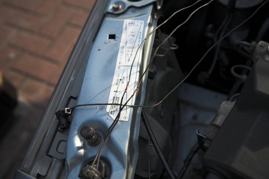
The theory was to re-insulate every wire back to a point in the loom where there is absolutely no sign of dererioration - and then go back a fair bit from that point too! This has left me with a connection point only just inside the engine bay just before the loom enters the bulkhead.
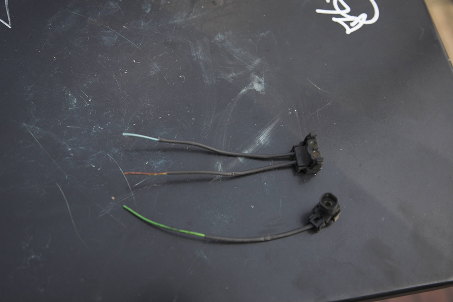
Where the loom is bad the insulation is rock hard and craks or just disintergrates when you touch it. The point I have sleeved back to has perfrct cables with normal flexibility and NO deterioration at all. Someone else may have to go all the way back to the ECU housing with the reinsulation!

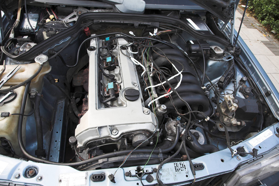
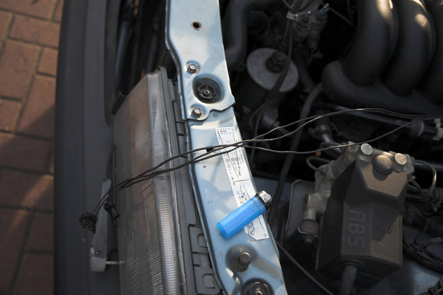
The white insulating tape is from my previous quick fix on the coilpack wiring and the individual injector looms. This is the harness in the main removed from the engine and the first individual wires unwrapped. By tomorrow all of the white tape will have been replaced using the method detailed below :)
2509050723_1cae2f7cbd_o.jpg


At each plug location the existing wires were cut about 4-6" from the end, then a single piece of 1.5mm heat shrink placed over the wire and shrunk into place. Then more heat shrink was added to the main wire all the way back to the bulkhead. This often entailed using 3 or 4 seperate lengths as the existing insulation would either crack or fall away completely making a single length of heat shrink almost impossible to apply. If this happens is not a problem just add a piece, shrink it then add a second pice and overlap it :)
2509050933_c554f01ed6_o.jpg


Now a pretty important part!
Once the wires have new insulation you need to add yet another length of bigger heat shrink (in my case 2.5mm) and run it about a foot up the loom out of the way.

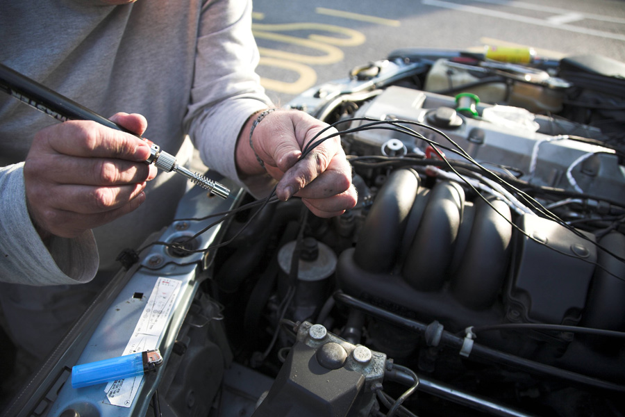
Now twist the wires together and solder them, I use a gas flame for both soldering and shrinking.

2509881076_f79616ce01_o.jpg


Having soldered the joint, you can now slide the big piece of heat shrink you fitted earleir back down over the joint and shrink to seal it. Pic courtesy of my son who turned up just in time :)
2509051519_281ffac512_o.jpg


The end result looks like this, - the wires are perfectly insulated and waiting to be bound with insulating tape first and then cloth loom tape :)

2509881804_fa13f942cd_o.jpg


I managed most wires except for the injectors and coilpacks in just 3 hours tonight and its looking really good now. Unfortunately it was also too late to get a finished pics of this section.
Tomorrow I will hopefully finish it and test every connection for resistance with a multimeter to ensure the accuracy of my soldering.

Then I hope to see that Bens mate is right and the car will suddenly cure itself - but I also wont be holding my breath!


Mark
 
Looking good, the advantage of using double heat shrink more than pays for its self as it always looks good with less chance of soldering up and find that you have forgoten the heat shrink.

The other advantage of using the double is that you can push it well out of the way of the soldered joint, and I have seen many joints where the heat shrink was too close the the joint and it shrinks where it is, and you cant move it.

Its looking good mark,, if it looks good then often it will be good

Heat shrink comes in
Black
clear
red
yellow
white
blue
green/yellow
browngrey
 
Last edited:
Excellent thread.

Excellent HOW TO which should be posted in the appropriate section when completed to your own satisfaction. A brief listing of the exact specification and source of materials used would be good sometime in the future.;) The transition point of degraded/sound insulation is yet another confirmation [if any was needed :( ] that its localised engine heat that causes the accelerated insulation breakdown.
 
Yesterday as shown above I did the front loom and temperature sensors

I did the lower engine loom today after work, including the big CTS sensor and then started on the injectors. I completed 1, 2 and 3 injectors and completely reinsulated and reloomed them . Now each individual injector has double heat shrunk cables inside a taped loom. This is very different to all injector wires being together in one bunch on the opriginal loom.

About another 2 hours should see it finished - but there is a rather important footy match on tonight!

I will try and take a few more pictures tomorrow night to show the final finish as well as how each of the injectors come together to form the final loom. If I can I will also try and cover the soldering and heatshrink.
 
I have finished the loom - and it made no difference at all :)
At least when I finally sort the issue I am pretty sure the loom will be good for a long time to come. When I put it all back together over the weekend I will take a series of pictures detailing the steps I took.


With just ign in the on position on there is a 12v feed to each injector, which is correct. Unfortunately if you run the multimeter across the injector plug this 12v finds its way to earth via the ECU on a permanent basis.

So now I'm on the hunt for an M104.994 S320 ECU !


Mark
 

Users who are viewing this thread

Back
Top Bottom