• The Forums are now open to new registrations, adverts are also being de-tuned.

W124 E200 with no ignition on cylinders 1 and 4

Just put my digital voltmeter across the low tension contacts of two coils and got a consistent reading of only 0.5 ohms for both. The secondary high tension outputs are difficult to test as there are two, one for each spark plug. Resistance between the outputs is infinite in both cases
 
As I suspected those figures I gave were garbage.
try
primary 0.3 to 0.6 ohms ----check

secondary 5.2 to 8.5 k ohms----??

Since the two HT outputs of each coil should be "floating" [see diagram] you could measure the secondary coil impedance with a megger-- which would also test the insulation on the HT side. Have you tried to measure the resistance of the known good coil with your DVM??
 
Hi Greame,
You are right I made a fundamental mistake on setting the range on my ohmmeter. The resistances are:
0.5 ohm for the primary
7.1 K ohms for the secondary
These values are consistent for the two Bosch (#0 221 505 437) coils I have checked. If there is a short causing the failure of my ECU/ignition control module I think I have ruled out the coils and now my attention is now on the low tension wiring..so far all looks OK

The only think is that altho the HT side will look OK on a DVM it will use a very low voltage to measure the impedance. It may be that at working voltages 25 kV the insulation on the secondary is breaking down- that's why I suggested using a megger to measure the coil insulation/resistance.
 
Check the coil resistances to earth as well. As you say, they're floating so measuring end to end wouldn't reveal a short to earth. While you're there, check there's infinite resistance between primary and secondary.
 
Thanks Greame for pointing this out, I confess I had over-looked this. I have no ready access to a megger but a thought occurred to me, if there is a fault specifically on the HT side of the coil what effect would this have on LT voltages and in turn the ECU output? My hope would be that since the high voltage in the HT side is as a direct result of the ECU triggered collapse of the voltage on the LT side, and therefore purely a passive event, that this should not exert much, if any, strain back on the ECU output transistors. Would not a break in HT lead insulation or cracked spark plug mimic the effect of HT output failure? If so, I am happy to suck and see the effect of a potentially duff coil so long as it does not put such a strain on the ECU to cause it to fail.
 
Stratman, I'll do this too. When all this over, and I am the owner of a rock solid car again, I will tie all the points together in one post
 
Thanks Greame for pointing this out, I confess I had over-looked this. I have no ready access to a megger but a thought occurred to me, if there is a fault specifically on the HT side of the coil what effect would this have on LT voltages and in turn the ECU output? My hope would be that since the high voltage in the HT side is as a direct result of the ECU triggered collapse of the voltage on the LT side, and therefore purely a passive event, that this should not exert much, if any, strain back on the ECU output transistors. Would not a break in HT lead insulation or cracked spark plug mimic the effect of HT output failure? If so, I am happy to suck and see the effect of a potentially duff coil so long as it does not put such a strain on the ECU to cause it to fail.

I think coil failure is usually initiated by heat stress in the coil itself. This may be part indirect from the engine itself or from internal heating of the coils. Altho "passive" the HT/LT windings are specifically designed for a very limited range of currents. Any deviation from these limits may precipitate failure. On the output HT side this is governed by the " load" resistance = spark plugs--- its dangerous to remove/reduce/ increase this "design load" as the HT voltage may find an alternative path to earth by arcing thus increasing the current in the output coils to levels higher than designed. Any overheated coils can also short lowering effective coil resistance and again increasing current beyond design limits. This can cause the insulation to fail allowing HT to " leak" into the low tension side or arc to earth causing RF currents which can feed into the ECU switching transistors--- these are low voltage devices and "they don't like it up em"
Don't know if I've explained that too well BUT:__
The rule is never run modern electronically switched HT coil ignition systems without an HT "load" if you can avoid it and if there is the slightest chance of defective coil HT leakage or arcing to the low tension side or a reduction in the coil windings resistance which can feed thro to the ECU don't risk it!
 
Hi Greame,
OK I have been busy, I checked everything. The coils are good, the wiring between the ECU and coils is good...no shorts.... and resistance of 0.3 ohms each. I determined that pins 10 and 11 on the PMS plug correspond to coil 1+4 and coil 2+3 respectively. I also managed to split my ECU apart and have determined the most likely cause of the fault. Because of the design and strength of the ECU casing and glue, gaining access to the interior of the ECU module certainly inflicts damage on many delicate internal connections to an extent that repair is not a feasible proposition.
I have made four 'power point' slides with photos and notes but cannot figure out how to post them herein, any advice in this regard would be welcome.
I swapped temporarily my wife's ECU for mine and I this fixed the issue of the lack of spark in cylinders 1 and 4. When my ECU packed up it was completely out of the blue and I now put it s failure down to nothing more than just old age.
 
If you scroll down from the blank " reply box" you will see a MANAGE ATTACHMENTS button. This opens a menu box where you can select files from your hard drive and post them as attachments to your post. There is a limit to image posted size 227KB for a jpg so you might have to use some form of image compression facility first. You can also link to the images [ any size] posted on an online open access site like Flickr. The older EZL ignition modules used to fail because the back was heat sinked to the wing via heat transfer compound - when this dried out they "cooked " eventually. Don' t know if this applies to the PMS modules or not??? It isn't necessary on the different design larger "metal finned" box of the HFM type
 
1. There are seven (7) sorts of trimming resistor and they are used to adjust the timing of ignition (number of degrees in advance or after TDC). 024 545 0628 is 110 ohm: 024 545 0728 is 4,750 ohms

Pin outs to the engine are:-
(These are not identified on the Bosch modules but are on the Siemens)
1 – 3 not used
4 injectors 1 and 4
5 idle speed control valve
6 power supply to throttle position sensor TPS (potentiometer), and idle speed control
7 signal input from coolant temperature sensor
8 signal input from idle speed control
9 ground for TPs, idle speed control, air temperature sensor and coolant temperature sensor
10 ignition coil for cylinders 1 and 4 (ignition triggered by ECU breaking the ground connection of the primary winding)
11 ignition coil for cylinders 2 and 3
12 if used then for factory fitted alarm/immobiliser system
13 injectors 2 and 3
14 idle speed control valve
15 signal input from TPS
16 signal input from air temperature sensor
17 signal from idle/throttle switch

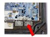
2. The base is metal and the circuit board is immersed in a silicone gel (has the consistency of jelly found in a meat pie). Arrows indicate the corresponding connections between the, now broken, wires from the circuit board on the left to the tabs on the right. The wires are very delicate as indeed are the connections indicating that very little current is used.

3. Most likely candidate for failure of ECU (no triggering for coil – cylinder 1 and 4). The connecting wire has become detached within the silicone and the area beneath shows a discoloured burn.

Note that the resistance on primary windings on the coils are 0.5 ohms and on the secondary winding 7,000 ohms. There should infinite resitance between primary and secondary and, indeed, with either and earth. The resistance of the loom between PMS and coils should be 0.3 ohms and again infinite resistance with earth. It might be a good idea to remove the engine connector with the PMS to check on the condition of the out pins on the PMS, it is the one area that shows quite a build up of white corrosion and may benefit from a rub down to fresh metal every decade or so :)
 

Attachments

  • New Picture (3).jpg
    New Picture (3).jpg
    31.8 KB · Views: 473
  • New Picture (2).jpg
    New Picture (2).jpg
    34.5 KB · Views: 459
  • New Picture.jpg
    New Picture.jpg
    41.7 KB · Views: 464
Sorted

A'new' ECu supplied by Neilrr has sorted the problem and I am now once again the owner of a working W124
 
Result= nice one neilrr :thumb:

Possibly the first time the "innards " of one of these ECU's has ever been seen on this forum.

Wonder if you simply wired in a couple of suitable heatsinked transistors to replace the ignition ones [ THE HFM ONES WOULD PROBABLY WORK? http://www.mbclub.co.uk/forums/engine/102590-ecu-ignition-output-transistors.html ] the "3 connections" ?? [ assuming the "2 connections" are diodes or something ] you could mount them in their own little heatsink box screwed to the wing on flying leads outside the main unit and then clapped the whole unit back together would it work? JUST THINKING ALOUD???
 
Last edited:
Hi Greame,
I too was under the impression that this ought to be fixable. In theory there is o difference between theory and practice, but in practice there is. To access the main board one would have to first access the central set of connections and this requires the removal first of the MAF unit from the top. This not easy as it is bonded in a recess in the top layer...simply not possible to lever it up without a bottom edge available. Assuming that you can get the top off all the connections would then have to be clipped between the main board and the surrounding tabs (see green arrows in above photo). These wires are very very weak, like spiders legs...a slight brush with the finger is enough to displace the join to the circuit board (the weight of a penny piece would cause them to collapse completely). Next the main board would have to revealed by now splitting the top panel from metal base plate. Only now is the wiring to the peripheral diodes/transistors revealed. I have fixed many devices in the past and this takes first place, by a long way, for being so delicate that it defies repair; it's like doing brain surgery while wearing boxing gloves!
 
It's all surface mounted components and laser welded, way too high tech and fragile. The casing is designed to deter all but the most intrepid and for good reason, it is a futile endeavour. It seems the later VDO type of ECU are of more conventional construction and are amenable to repair. 'Non serviceable parts inside' is an accurate warning for PMS ECUs.
 
Well done Joe for going where few have feared to tread. Thanks to you we all now know that if one of these PMS ECU's "pegs out" that they are a lost cause. The big ECU repairers probably knew this already but their judgement is perhaps going to be biased by the economics of repair to a certain extent rather than whether it's ultimately possible or not. It would be interesting to know what proportion of M111 engines out there had this injection/ECU set up from the factory? Some late W124's and early W202's I would guess.?
 
My educated guess is that W124s from 93 to the last of the run in early 96 with the M111 engine had PMS ignition. The Haynes W124 manual does not cover it as it only covers cars up to 93. The early W202 cars also with the M111 engine also had PMS. These cars had the added sophistication of a cam sensor which allowed a more sophisticated and more economical injection regime. The Haynes W202 manual does cover this and for m111 engine matters is a better manual than that for the W124.
As for the ECU repairers I hope that none are cynically offering to inspect PMS modules of this type with a view to repair and collecting £50 in the sure knowledge that they are irreparable. The need to replace coils along with the ECU is moot. My approach would be to first to swap the coils over, so that a known good coil is positioned where the suspect bad coil was and vice versa. If the ECU now burns out the last remaining power transistor then you know it is bad coil; the total loss of the ECU (PMS type specifically) is no disaster as it was fried already and we now know is beyond repair anyway. If the engine fires on the same two cylinders at least you can be pretty sure of the coils. To make doubly sure check for continuity, resistance of both primary and secondary coils along with no shorts between them or to ground. Last check the wiring loom from pin outs 10 and 11 on the ECU plug all the way to the primary coil connection for low resistance and no shorts. To have a 'new' second PMS ECU fail after these precautions would be exceedingly unlikely.
 

Users who are viewing this thread

Back
Top Bottom